
Motorcycle parts conveying device

A technology for conveying devices and parts, applied in metal processing machinery parts, maintenance and safety accessories, other manufacturing equipment/tools, etc., can solve problems such as reduced work efficiency and wear of hardware blocks, so as to prolong service life and reduce defective products Efficiency, driving mode and environmental protection effect

Inactive Publication Date: 2018-09-18
重庆荣爵摩托车有限公司
View PDF10 Cites 4 Cited by
  • Summary
  • Abstract
  • Description
  • Claims
  • Application Information

AI Technical Summary

Problems solved by technology

[0004] But there are following problems in the above-mentioned scheme: 1, because the grinding and polishing process in the prior art is finished by drilling drill bit and grinding cylinder body respectively, and drilling drill bit and grinding cylinder body are two separate parts, and because punching The drill bit and the frosted cylinder move up and down synchronously, so when the drill bit is drilling the hardware block, the frosted cylinder moves downward with the drill bit, and the frosted cylinder may cause wear to other parts of the hardware block
2. On the drilling production line, the workpiece needs to be manually placed on and removed from the workbench, and the temperature of the workpiece is high due to the high-speed friction between the drill bit and the workpiece during processing, and the operator needs to place the workpiece for a period of time After taking it off, the work efficiency will be greatly reduced

Method used


Image

  • Motorcycle parts conveying device
  • Motorcycle parts conveying device

Examples


Embodiment Construction

[0020] The present invention will be described in further detail below by means of specific embodiments:

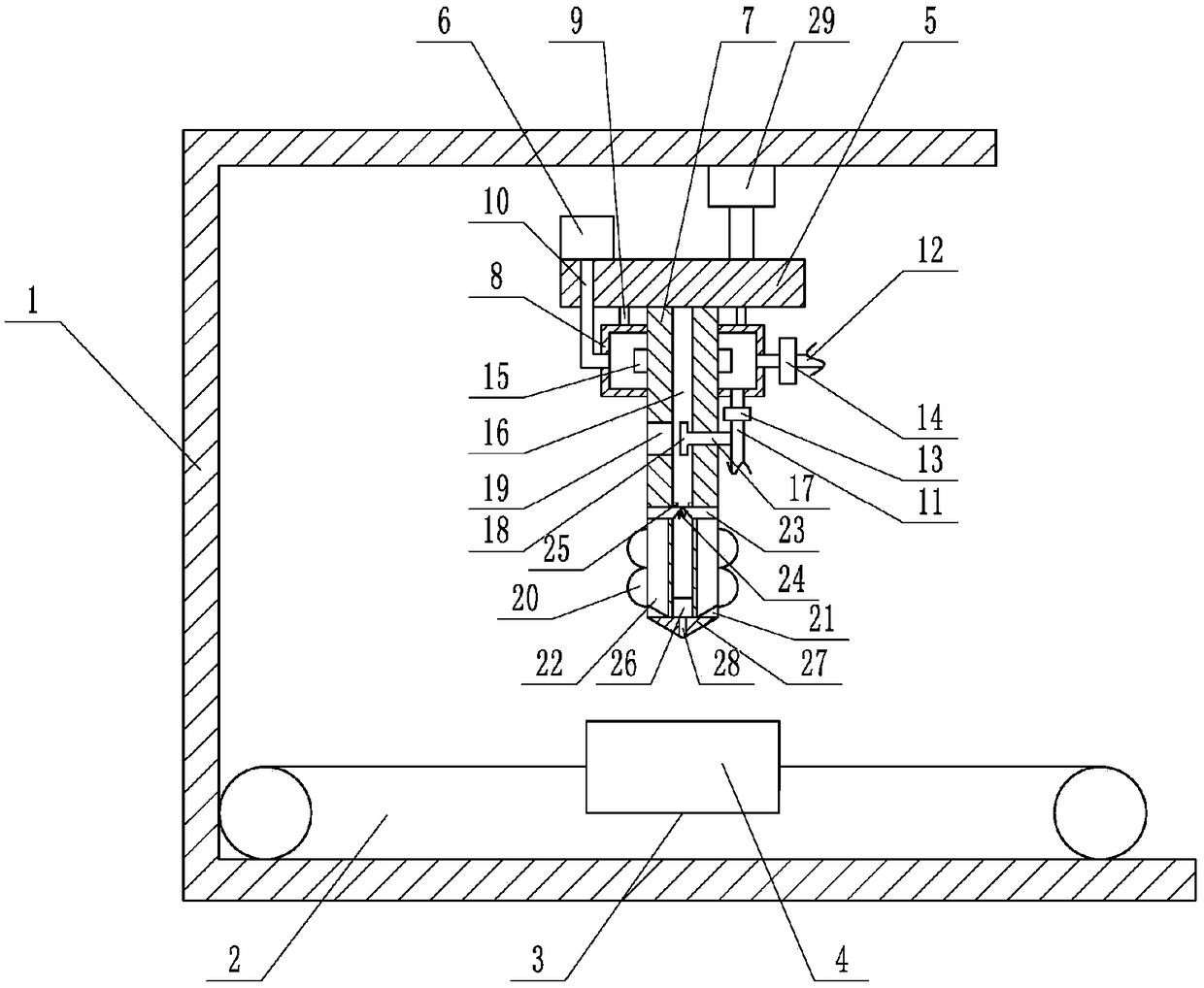
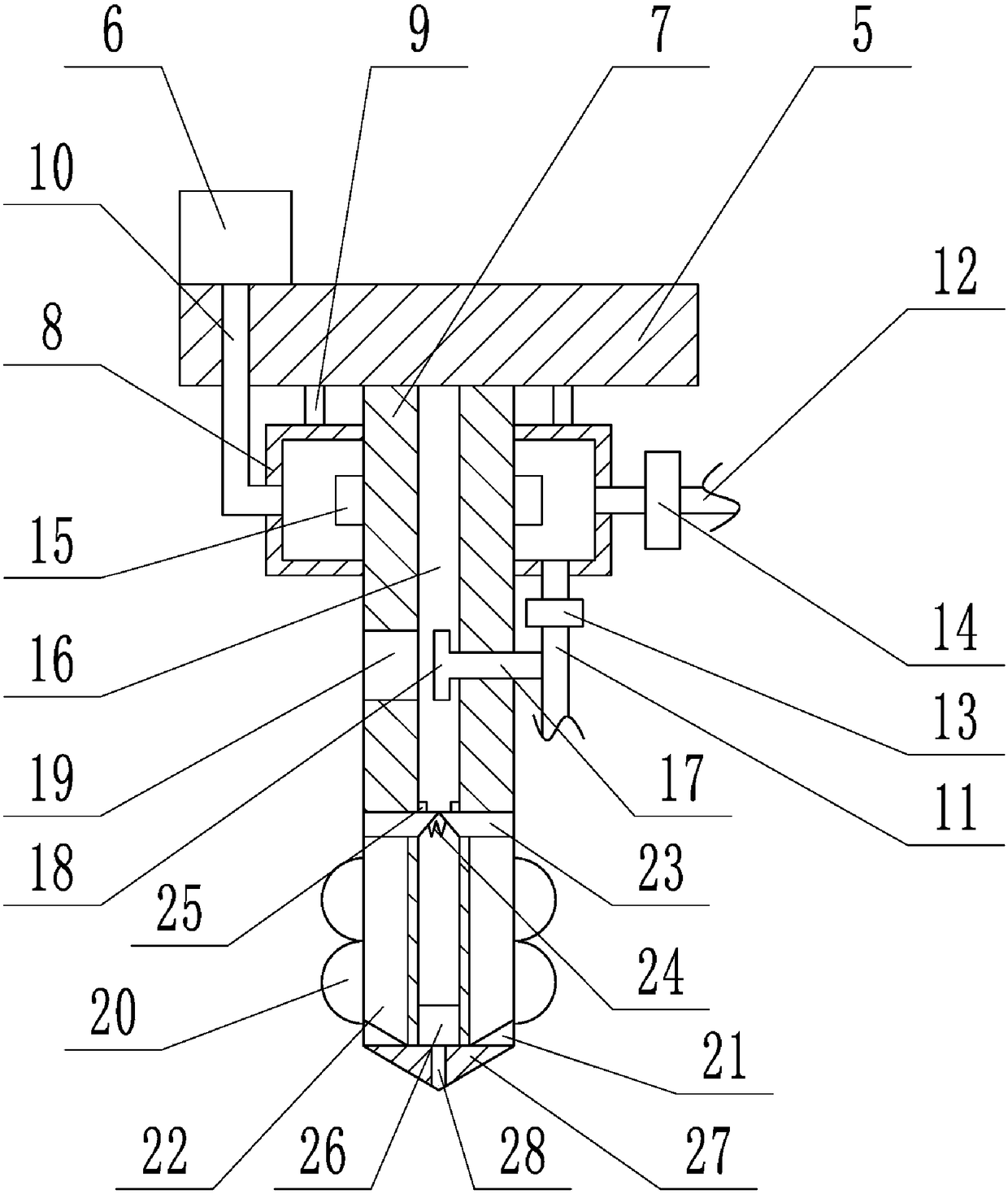
[0021] The reference signs in the accompanying drawings of the description include: frame 1, conveyor belt 2, groove 3, workpiece 4, slide plate 5, blower 6, rotating rod 7, air intake chamber 8, first connecting rod 9, air intake pipe 10, the first One exhaust pipe 11, second exhaust pipe 12, first valve 13, second valve 14, fan blade 15, sliding hole 16, second connecting rod 17, negative pressure blade 18, exhaust port 19, frosted ball 20 , Chute 21, blade 22, wedge 23, spring 24, position-limiting protrusion 25, briquetting block 26, drill bit 27, air hole 28, cylinder 29.

[0022] Such as figure 1 and figure 2 As shown, the motorcycle parts delivery device includes a frame 1, a transmission mechanism and a drilling mechanism, the transmission mechanism is fixed on the frame 1, the drilling mechanism is slidingly connected to the frame 1, and the cylinder is fixed ...


PUM


Abstract

The invention belongs to the technical field of material conveying devices, and particularly relates to a motorcycle parts conveying device which comprises a rack. A drilling mechanism is slidably connected onto the rack; a conveying mechanism is further fixedly arranged on the rack; the drilling mechanism comprises a slide plate and a rotary rod; the rotary rod is rotatably connected with the slide plate; an air inlet chamber is rotatably connected onto the rotary rod; a first exhaust pipe is arranged on the air inlet chamber; a blade is arranged on the rotary rod in an air inlet pipe; a slide hole is formed in the rotary rod; a wind wheel is rotatably connected into the first exhaust pipe and is coaxially provided with a negative pressure blade; the negative pressure blade is located inthe slide hole; two sliding chutes are formed in the rotary rod; cutting blades are slidably connected into the two sliding chutes; check blocks are fixedly arranged on the cutting blades; a pressingblock is arranged in the slide hole; a drill bit is arranged on the rotary rod; an air hole is formed in the drill bit; and a dull polish ball is further arranged on the rotary rod. The motorcycle parts conveying device provided by the invention can be adopted for punching, grinding and polishing a workpiece, so that an operation process is simplified; and the motorcycle parts conveying device isusually used for punching motorcycle parts.

Description

technical field [0001] The invention belongs to the technical field of material transportation devices, and in particular relates to a motorcycle parts transportation device. Background technique [0002] During the production and processing of motorcycle parts, parts are drilled for assembly, aesthetics, weight reduction and other considerations. However, the existing drilling technology has the disadvantages of low work efficiency, uneven drilling, and rough holes. [0003] For this reason, Chinese patent CN106151239A discloses a kind of punching device of hardware block, comprises L-shaped plate, and the inner top of L-shaped plate is provided with slide block and first guide wheel, is connected between slide block and L-shaped plate. A spring, a T-shaped plate is arranged above the L-shaped plate, a guide hole and a second spring are arranged on the T-shaped plate, the lifting rod passes through the guiding hole, a moving plate is arranged on the lifting rod, a first mot...

Claims


Application Information

Patent Timeline
IPC IPC(8): B23P23/04B23Q11/10B23Q11/00B23Q7/00
CPCB23P23/04B23Q7/00B23Q11/005B23Q11/10
Inventor 杨雨涵
Owner 重庆荣爵摩托车有限公司
Learn More