
Duplex I-shaped energy dissipation device and supporting structure thereof

A technology of energy-dissipating devices and supporting structures, which is applied in the direction of building components, building types, building structures, etc., can solve the problems of low yield point steel plate cost, expensive energy-dissipating device accessories, and large impact on energy-dissipating device performance. Achieve the effect of simple and reasonable structure arrangement, convenient and quick installation, and reduce production cost

Pending Publication Date: 2018-09-18
SOUTHEAST UNIV +2
View PDF0 Cites 4 Cited by
  • Summary
  • Abstract
  • Description
  • Claims
  • Application Information

AI Technical Summary

Problems solved by technology

[0004] In recent years, shock absorption technology has gradually been used in my country, but most of the energy-consuming devices are imported products from abroad, the product cost is relatively high, and the related accessories of energy-consuming devices are also very expensive, which largely limits its domestic use. Widely promoted, only applied in a small number of important projects
In view of this situation, many domestic scholars have carried out relevant research on energy-dissipating devices. Considering that low-yield-point steel has better deformation capacity, low-yield-point steel plates have become the main material for energy-dissipating devices, but low-yield The cost of point steel plates is not cheap, and welding is mainly used for processing, and the splicing welds between steel plates have a great impact on the performance of energy consumers

Method used


Image

  • Duplex I-shaped energy dissipation device and supporting structure thereof
  • Duplex I-shaped energy dissipation device and supporting structure thereof
  • Duplex I-shaped energy dissipation device and supporting structure thereof

Examples


Embodiment Construction

[0045] The technical solution of the present invention will be further described below in conjunction with the accompanying drawings.

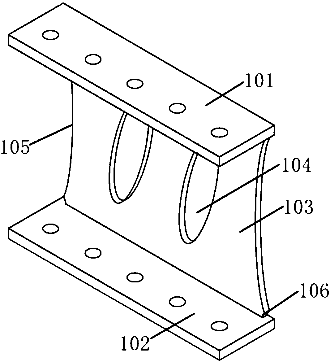
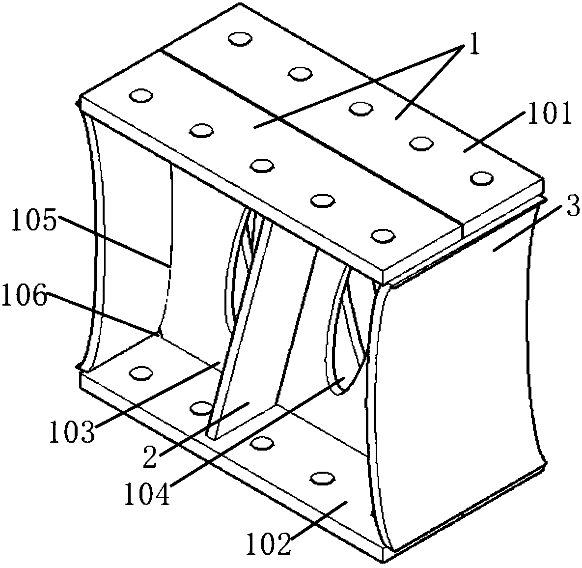
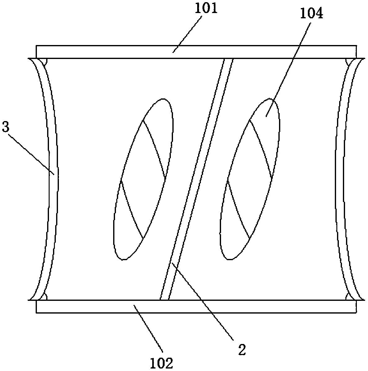
[0046] like figure 1 and 2 As shown, the present invention discloses a double-combined I-shaped energy dissipation device, which includes two energy dissipation panels 1 , a stiffening panel 2 and an arc-shaped sealing panel 3 arranged at intervals with their backs facing each other. The stiffening plate 2 and the arc-shaped sealing plate 3 are also preferably Q235 steel plates. Wherein the energy dissipation plate 1 is a U-shaped plate integrally formed by the upper wing plate 101, the lower wing plate 102 and the web 103, and the parallelism error of the inner and outer surfaces of the upper wing plate 101 and the lower wing plate 102 is less than 0.5mm; Energy plate 1 can be made by cutting hot-rolled Q235H section steel along one side of the web to remove redundant wings, among which ultra-high pressure water jet cutting or wire cutting ...


PUM


Abstract

The invention discloses a duplex I-shaped energy dissipation device. The duplex I-shaped energy dissipation device comprises two energy dissipation plates oppositely arranged in a spaced mode, reinforcing plates obliquely arranged in each energy dissipation plate and an arc-shaped sealing plate fixedly connected with the two energy dissipation plates. Each energy dissipation plate is a U-shaped plate integrally formed by an upper wing plate, a lower wing plate and a web plate. A plurality of oblique elliptical holes are formed in the web plates. Arc-shaped end faces consistent with the radianof the arc-shaped sealing plate are formed in the end faces of the two sides of each web plate. The arc-shaped end faces and the arc surface of the arc-shaped sealing plate are fixed together. The upper wing plates and the upper end face of the arc-shaped sealing plate are fixed together, and the lower wing plates and the lower end face of the arc-shaped sealing plate are fixed together. In the duplex I-shaped energy dissipation device, the upper wing plate, the lower wing plate and the web plate of each energy dissipation plate are of an integrally-formed structure, the situation that the phenomenon that weld seams cracks and damage occur at the end corner points of the welding connecting positions of the web plates and the wing plates, and consequently, the capacity that the energy dissipation device cooperates with a building structure to dissipate seismic energy is lost in advance by the energy dissipation device is avoided, and it is ensured that under the action of an earthquake,the effect of dissipating the energy of the energy dissipation device can be fully achieved.

Description

technical field [0001] The invention relates to an anti-seismic energy consumption device in construction engineering, in particular to a double-combined I-shaped energy consumption device and its supporting structure. Background technique [0002] my country is located between the world's two major earthquake zones and is one of the countries with many earthquakes. Earthquakes are characterized by strong suddenness and great destructiveness. There are three main ways to prevent earthquake disasters in current construction projects, namely, anti-seismic, seismic isolation and shock absorption. Seismic resistance is to increase the amount of materials used in building structures so that the structure itself has sufficient ability to resist earthquakes. At present, the main method of seismic resistance in my country is to carry out seismic design of building structures. Seismic isolation is to set a seismic isolation layer between the top of the building foundation and the su...

Claims


Application Information

Patent Timeline
Patent Type & Authority Applications(China)
IPC IPC(8): E04B1/58E04B1/24E04B1/98E04H9/02
CPCE04B1/2403E04B1/98E04H9/021E04B2001/2448Y02E10/50
Inventor 郭正兴林煜
Owner SOUTHEAST UNIV
Learn More