
Energy-saving and environment-friendly combustion furnace

An energy-saving and environmentally friendly combustion furnace technology, which is applied in the direction of combustion methods, combustion equipment, and treatment of combustion products, can solve problems such as coal waste, environmental pollution, and insufficient coal combustion, and achieve the effect of sufficient combustion

Active Publication Date: 2018-09-18
南通高新工业炉有限公司
View PDF5 Cites 8 Cited by
  • Summary
  • Abstract
  • Description
  • Claims
  • Application Information

AI Technical Summary

Problems solved by technology

[0005] Aiming at the deficiencies of the prior art, the present invention provides an energy-saving and environment-friendly combustion furnace, which has the advantages of being convenient for coal combustion, adding fuel during use, and purifying flue gas. When fuel is added to the door of the combustion furnace, a large amount of flue gas in the combustion furnace gushes out, thereby polluting the environment, and common boilers cannot control the internal air volume, resulting in insufficient coal combustion, resulting in waste of coal, and coal burning The flue gas generated in the end is directly discharged without treatment, which also causes pollution to the environment.

Method used


Image

  • Energy-saving and environment-friendly combustion furnace
  • Energy-saving and environment-friendly combustion furnace
  • Energy-saving and environment-friendly combustion furnace

Examples


Embodiment Construction

[0026] The following will clearly and completely describe the technical solutions in the embodiments of the present invention with reference to the accompanying drawings in the embodiments of the present invention. Obviously, the described embodiments are only some, not all, embodiments of the present invention. Based on the embodiments of the present invention, all other embodiments obtained by persons of ordinary skill in the art without making creative efforts belong to the protection scope of the present invention.

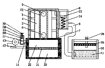
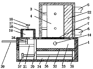
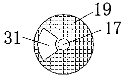
[0027] see Figure 1-3, an energy-saving and environment-friendly combustion furnace, comprising a bottom furnace 1, a top furnace 2 is fixedly installed on the top of the bottom furnace 1, and a fixed rod 3 is fixedly installed on the inner wall of the top furnace 2, and the number of the fixed rods 3 is six, and the six Two fixed rods 3 are symmetrically distributed on the inner walls of the two sides and the back of the top furnace 2, and the ends of the si...


PUM


Abstract

The invention relates to the field of boiler equipment, and discloses an energy-saving and environment-friendly combustion furnace. The energy-saving and environment-friendly combustion furnace comprises a bottom furnace, wherein a top furnace is fixedly arranged on the top of the bottom surface; six fixed rods are fixedly arranged on the inner wall of the top furnace; the six fixed rods are pairwise grouped and are symmetrically distributed on the inner walls of the two side surfaces and the back surface of the top furnace; and the end, far away from the top furnace, of each fixed rod is fixedly connected to the same boiler. The energy-saving and environment-friendly combustion furnace has the beneficial effects that a draught fan enables air to enter a combustion chamber so as to ensurethe sufficient combustion of coal, and meanwhile, a sealing plug is adjusted to move up and down by rotating a threaded rod, so that the flow rate of air is controlled, the content of air in the combustion chamber is controlled, the content of oxygen in the combustion chamber is appropriate, the coal is fully combusted, and the problem that as a common boiler cannot control the content of internalair, the coal combustion is insufficient, and the wasting of the coal is caused is solved.

Description

technical field [0001] The invention relates to the field of boiler equipment, in particular to an energy-saving and environment-friendly combustion furnace. Background technique [0002] The original meaning of the pot refers to the water container heated on the fire, and the furnace refers to the place where fuel is burned. The boiler includes two parts: the pot and the furnace. The hot water or steam generated in the boiler can directly provide the required heat energy for industrial production and people's life, and can also be converted into mechanical energy through a steam power device, or converted into electrical energy through a generator. Boilers that provide hot water are called hot water boilers, which are mainly used in daily life, and also have a small amount of application in industrial production. [0003] However, during the use of common boilers, when the door of the combustion furnace is opened to add fuel again, a large amount of flue gas in the combust...

Claims


Application Information

Patent Timeline
IPC IPC(8): F24H1/34F24H9/18F23B40/06F23J1/00F23J11/00F23J15/02F23L5/02F23L13/06
CPCF23B40/06F23J1/00F23J11/00F23J15/02F23L5/02F23L13/06F24H1/34F24H9/189
Inventor 张孝法
Owner 南通高新工业炉有限公司
Learn More