Wastewater centrifugal filtering device for water jet loom

A technology of centrifugal filtration and water jet loom, which is applied in the direction of looms, filtration separation, auxiliary weaving equipment, etc. It can solve the problems of large volume of filtration devices, reduce work efficiency, occupy factory space, etc., and achieve short filtration time and high working efficiency. The effect of high efficiency and low production cost

Pending Publication Date: 2018-09-21
陈启发
View PDF4 Cites 2 Cited by
  • Summary
  • Abstract
  • Description
  • Claims
  • Application Information

AI Technical Summary

Problems solved by technology

However, multi-layer filtration is required in this filter device, which takes a long time to filter, which reduces the work efficiency. At the same time, in order to ensure that the filtered water can be supplied to the water jet loom in time, a larger water collection tank is required, causing the whole The filter device is too large, which not only occupies limited workshop space, but also is not conducive to the convenient installation of the whole device
In addition multiple filter layers require more filter material, so the production cost of the whole device is higher

Method used


Image

  • Wastewater centrifugal filtering device for water jet loom
  • Wastewater centrifugal filtering device for water jet loom
  • Wastewater centrifugal filtering device for water jet loom

Examples


Embodiment 1

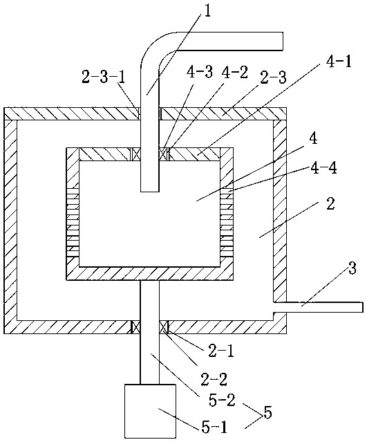
[0026] Such as figure 2As shown, the driving device 5 includes a motor 5-1 arranged on the outside of the filter box 2 and a rotating shaft 5-2 for connecting the filter cartridge 4 and the motor 5-1, and the bottom of the filter box 2 is provided with a rotating hole 2-1 , and a rotating bearing seat 2-2 is set in the rotating hole 2-1, and the rotating shaft 5-2 passes through the rotating bearing seat 2-2 and is connected with the filter cartridge 4. At the same time, it should be ensured that the rotating bearing seat 2-2 is an oil seal to prevent water from flowing out of the bearing seat. The distance between the bottom of the filter cartridge 4 and the bottom of the filter box 2 is 25 cm. The central axis of the rotating shaft 5 - 2 coincides with the central axis of the filter cartridge 4 . The motor 5-1 that drives the filter cartridge 4 to rotate is arranged outside the filter box 2, without using a waterproof motor, which can reduce the manufacturing cost of the ...

Embodiment 2

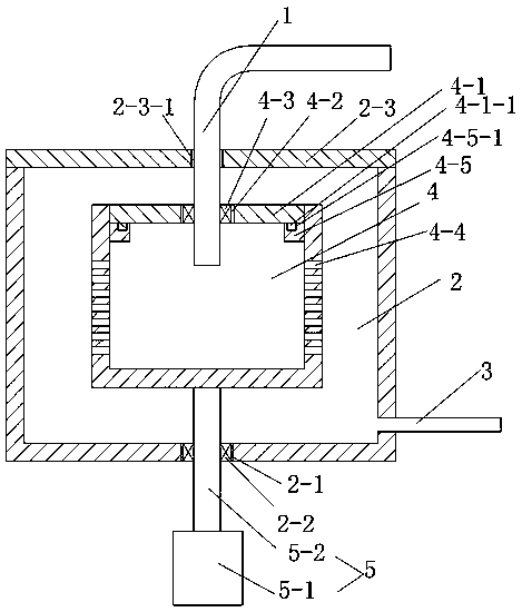
[0028] Such as image 3 As shown, on the basis of the arrangement of the driving device 5 in Embodiment 1, the cover plate 4-1 is movably connected with the filter cartridge 4, the inner wall of the filter cartridge 4 is provided with internal threads, and the outer wall of the cover plate 4-1 is provided with the inner thread. External thread for thread fit. The cover plate 4-1 is movably connected with the filter cartridge 4, and the filter material in the filter cartridge 4 can be replaced by opening the cover plate 4-1, thereby improving the filtering effect. At the same time, the external thread on the cover plate 4-1 cooperates with the internal thread on the inner wall of the filter cartridge 4 to fix the relative position of the cover plate 4-1 and the filter cartridge 4, which can ensure the connection strength of the two, and at the same time make the entire cover The installation and removal of the board 4-1 is more convenient.

Embodiment 3

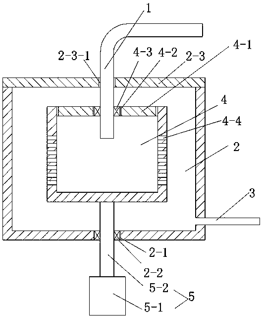
[0030] Such as Figure 4 As shown, on the basis of the arrangement of the driving device 5 in the first embodiment, the cover plate 4-1 is fixedly connected with the filter cartridge 4, specifically by welding. Fixing by welding can not only ensure the connection strength between the cover plate and the filter cartridge, but also ensure the sealing of the cover plate, preventing waste water from flowing out from the gap between the cover plate and the filter cartridge and affecting the entire filtering effect.


PUM


Abstract

The invention relates to a wastewater centrifugal filtering device for a water jet loom. The wastewater centrifugal filtering device comprises a water intake pipe, a filtering box and a water drain pipe, wherein the water drain pipe is connected with the filtering box; a filtering cylinder and a driving device are arranged in the filtering box, and the driving device is used for driving the filtering cylinder to rotate; the filtering cylinder is of a cylindrical structure of which the upper end is provided with an opening; a cover plate is arranged at the opening; the cover plate is provided with a water inlet and a bearing block, and the bearing block is connected with the water inlet; the water intake pipe penetrates through the bearing block and enters the filtering cylinder; a circularhole is formed in the side wall of the filtering cylinder, and is used for allowing a water body to penetrate through. The wastewater centrifugal filtering device has the advantages that by arrangingthe filtering cylinder with the circular hole and the driving device for driving the filtering cylinder to rotate, the wastewater of the water jet loom is sent into the filtering cylinder, and is directly subjected to centrifugal filtering; compared with other filtering devices for treating the wastewater by multiple filtering layers, the filtering time is shorter, the working efficiency is higher, the arrangement of multiple filtering materials is not needed, and the production cost is lower.

Description

technical field [0001] The invention relates to the technical field of textile equipment, in particular to a wastewater centrifugal filter device for a water jet loom. Background technique [0002] The water-jet loom is a shuttleless loom that uses a jet of water to pull the weft through the shed. Water-jet weft insertion has greater friction and traction on weft yarn than air-jet weft insertion, and has less diffusivity, which is suitable for weft insertion of filaments such as synthetic fibers and glass fibers with smooth surfaces. However, water jet looms will produce a large amount of waste water containing textile fibers while weaving. In order to save the water consumed by the water jet loom, waste water is generally treated and then recycled. [0003] For example, a waste water filter device for water jet loom disclosed in patent announcement number CN205740541U, the top of the water collection tank is provided with a water inlet, and a first filter chamber is insta...

Claims


Application Information

Patent Timeline
Patent Type & Authority Applications(China)
IPC IPC(8): D03D47/32D03J1/00B01D33/11B01D33/80
CPCB01D33/11B01D33/801D03D47/32D03J1/00
Inventor 陈启发
Owner 陈启发
Why Eureka
Try Eureka