Rotor supporting structure of turbine machines

A technology of rotor support and turbomachinery, applied in mechanical equipment, engine components, machines/engines, etc., can solve problems that affect the design cycle of the unit, operation safety and reliability, and vibration characteristics due to many factors and complex vibration characteristics. The adjustment method is simple and easy, the design difficulty is reduced, and the effect of improving the dynamic stiffness

Inactive Publication Date: 2018-09-21
DONGFANG TURBINE CO LTD
View PDF6 Cites 1 Cited by
  • Summary
  • Abstract
  • Description
  • Claims
  • Application Information

AI Technical Summary

Problems solved by technology

Controlling the vibration characteristics by adjusting the support structure requires accurate calculation, design and manufacture to ensure, but for the cylinder of the turbomachinery, its vibration characteristics are complex, there are many factors affecting the vibration characteristics, the calculation is difficult, and the calculation accuracy is low. Difficulties have greatly affected the design cycle and operational safety and reliability of the unit

Method used


Image

  • Rotor supporting structure of turbine machines
  • Rotor supporting structure of turbine machines
  • Rotor supporting structure of turbine machines

Examples


Embodiment 1

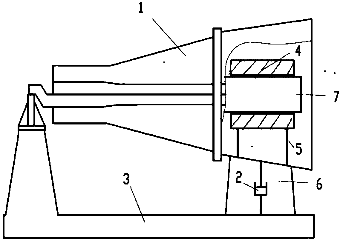
[0023] Embodiment 1: as figure 1 , 2 As shown, the damper 2 is installed between the cylinder 1 and the fixed foundation 3. When the unit is running, the dynamic excitation force generated by the rotation of the rotor 7 is transmitted to the cylinder 1 through the bearing box 4, and the cylinder 1 transmits the vibration to the damper 2 and drives The damper 2 moves, and the movement of the damper 2 dissipates the vibration energy, reduces the vibration amplitude of the cylinder 1, and improves the support dynamic stiffness of the cylinder 1.

Embodiment 2

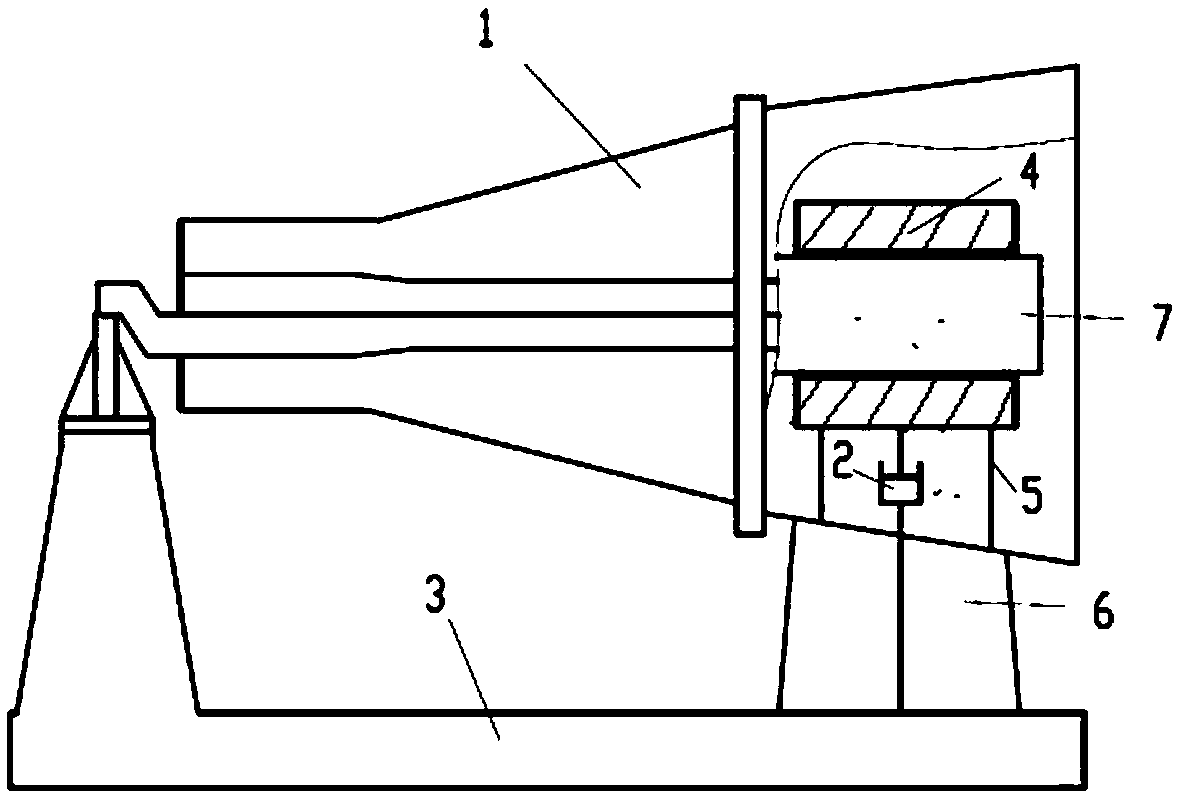
[0024] Embodiment 2: as image 3 , 4 As shown, the damper 2 is installed between the bearing box 4 and the fixed foundation 3. When the unit is running, the dynamic excitation force generated by the rotation of the rotor 7 is transmitted to the damper 2 through the bearing box 4 and drives the damper 2 to move, and the damper The movement of 2 dissipates the vibration energy, reduces the vibration amplitude of the bearing box 4, and improves the supporting dynamic stiffness of the bearing box 4.

Embodiment 3

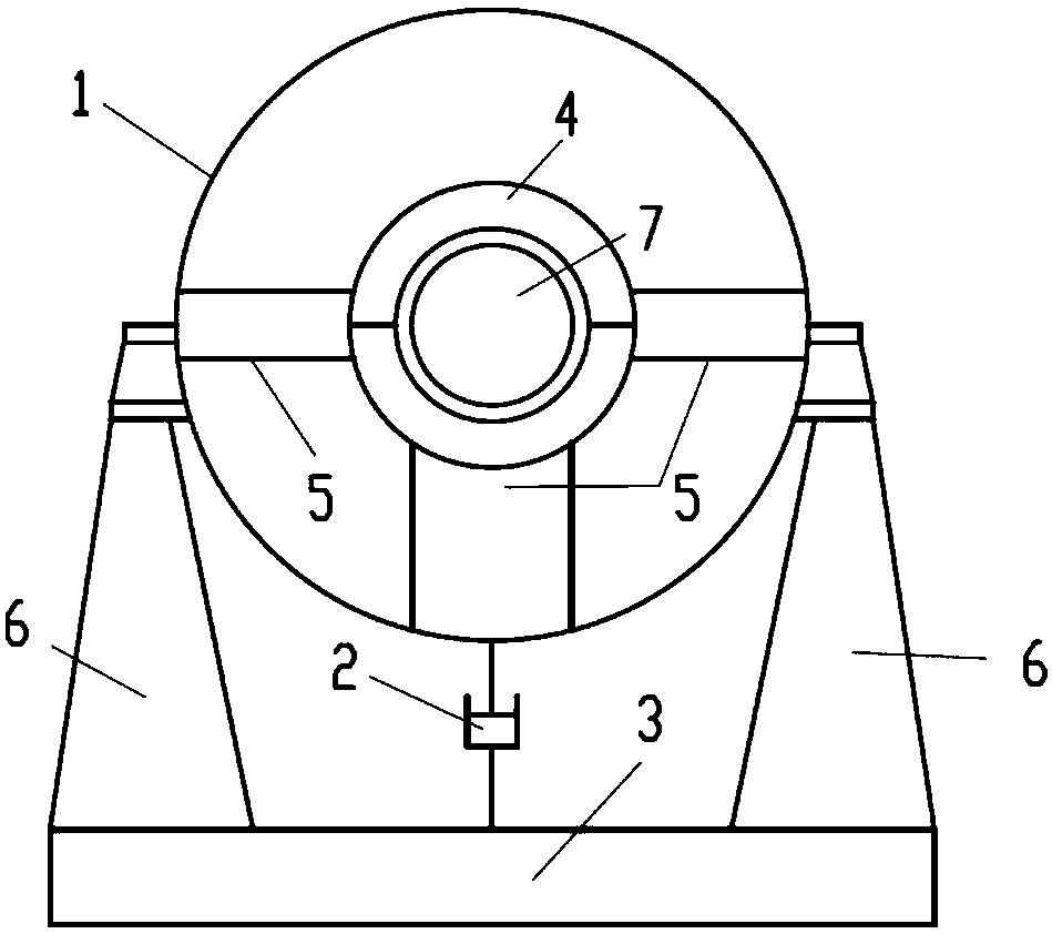
[0025] Embodiment 3: as Figure 5 , 6 As shown, the damper 2 is installed between the cylinder 1 and the bearing box 4. When the unit is running, the dynamic excitation force generated by the rotation of the rotor 7 is transmitted to the damper 2 through the bearing box 4 and drives the damper 2 to move, and the damper 2 The movement dissipates the vibration energy, reduces the amplitude of the bearing 4 and the cylinder 1, and improves the support dynamic stiffness of the bearing box 4 and the cylinder 1.

[0026] Since the damper 2 is added to the traditional rotor support structure, the vibration transmitted to the damper 2 by the above-mentioned other supporting structure components drives the damper 2 to move to realize energy consumption, suppress vibration and improve dynamic stiffness. Therefore, the damping When the damper 2 is installed at different positions, its effect is different. Generally, the damper 2 is installed at the position where the rotor support struc...


PUM


Abstract

The invention discloses a rotor supporting structure of turbine machines. The rotor supporting structure comprises a fixed foundation (3), an air cylinder floor support (6), an air cylinder (1), a bearing box (4) and a bearing box and air cylinder connecting support (5) and further comprises at least one damper (2). The rotor supporting structure is simple, easy to implement and low in cost, the design difficulty of a turbine mechanical support can be remarkably lowered, safety of turbine mechanical operating is improved effectively, the design period is shortened, and the rotor supporting structure is particularly suitable for the medium and small turbine machines with rotors being supported through the air cylinder.

Description

technical field [0001] The invention relates to a turbomachinery support, in particular to a support structure for a turbine unit with a rotor falling into a cylinder structure. Background technique [0002] Turbine machinery is an important industrial equipment, which is widely used in power industry, petrochemical industry, power drag and other fields. It consists of a rotor part and a stator part. Among them, the cylinder is its most important stator component. For turbomachinery, the vibration and fatigue problems caused by the dynamic excitation force generated by the rotation of the rotor parts are the most important factors affecting the safety of the equipment, especially for the rotor with the cylinder structure unit supported by the cylinder, this problem is even more serious To highlight, the intensity of this vibration is closely related to the dynamic stiffness of the rotor support, and the greater the dynamic stiffness of the rotor support, the easier it is t...

Claims


Application Information

Patent Timeline
IPC IPC(8): F01D25/28F01D25/04F01D25/16
CPCF01D25/04F01D25/164F01D25/28
Inventor 张晓东赵仕志
Owner DONGFANG TURBINE CO LTD
Why Eureka
Try Eureka