Waste-heat recycling device for cooling industrial oil

A waste heat recovery device and industrial oil technology, applied in the direction of filtration circuit, indirect heat exchanger, heat exchanger type, etc., can solve the problems of reducing the working efficiency of industrial oil processing, wasting time and cost, and environmental damage, etc., to increase Production quality, avoidance of environmental pollution, effect of environmental protection

Inactive Publication Date: 2018-09-21
吴超
View PDF0 Cites 1 Cited by
  • Summary
  • Abstract
  • Description
  • Claims
  • Application Information

AI Technical Summary

Problems solved by technology

[0002] In the process of processing industrial oil, it is necessary to implement cooling treatment. The general treatment method is to blow air directly through a high-power fan to improve the heat exchange efficiency. This method not only reduces the working efficiency of industrial oil processing, but also It greatly wastes the customer's time and cost. At the same time, a large amount of waste heat is generated in the cooling process of industrial oil. In many cases, a large amount of waste heat is often generated. If these waste heat are directly discharged into the environment, it is likely to cause environmental damage. At the same time, it will inevitably cause a lot of waste of energy. At the same time, the remaining mechanical impurities, ash and residual carbon in the industrial oil after production are all quality indicators reflecting the purity of the oil and the degree of refining of the lubricating base oil.

Method used


Image

  • Waste-heat recycling device for cooling industrial oil
  • Waste-heat recycling device for cooling industrial oil
  • Waste-heat recycling device for cooling industrial oil

Examples


Embodiment 1

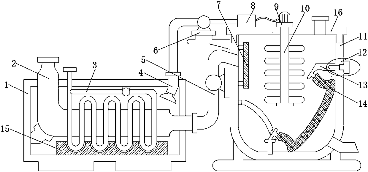
[0018] Example 1: Reference Figure 1-3 , a waste heat recovery device for industrial oil cooling, the cooling liquid is injected into the cooling water pipe 3 through the inlet of the cooling water pipe 3 exposed at the outer end of the cooling box 1, and under the action of the circulating pump connected to the upper end, the cooling liquid can be The cooling water pipe 3 circulates in circulation, and then the industrial oil that needs to be cooled is injected into the circulation pipe 2 through the open end of the circulation pipe 2, so that the high-temperature industrial oil flows through the circulation pipe 2 to the next connected pipe. When flowing in the circulation pipe 2, the cooling water pipe 3 wrapped around the outer wall of the circulation pipe 2 will cool the oil in the circulation pipe 2, and the cooling liquid will circulate in the cooling water pipe 3 to generate cold air and oil in the circulation pipe 2. The steam generated by the liquid undergoes heat e...

Embodiment 2

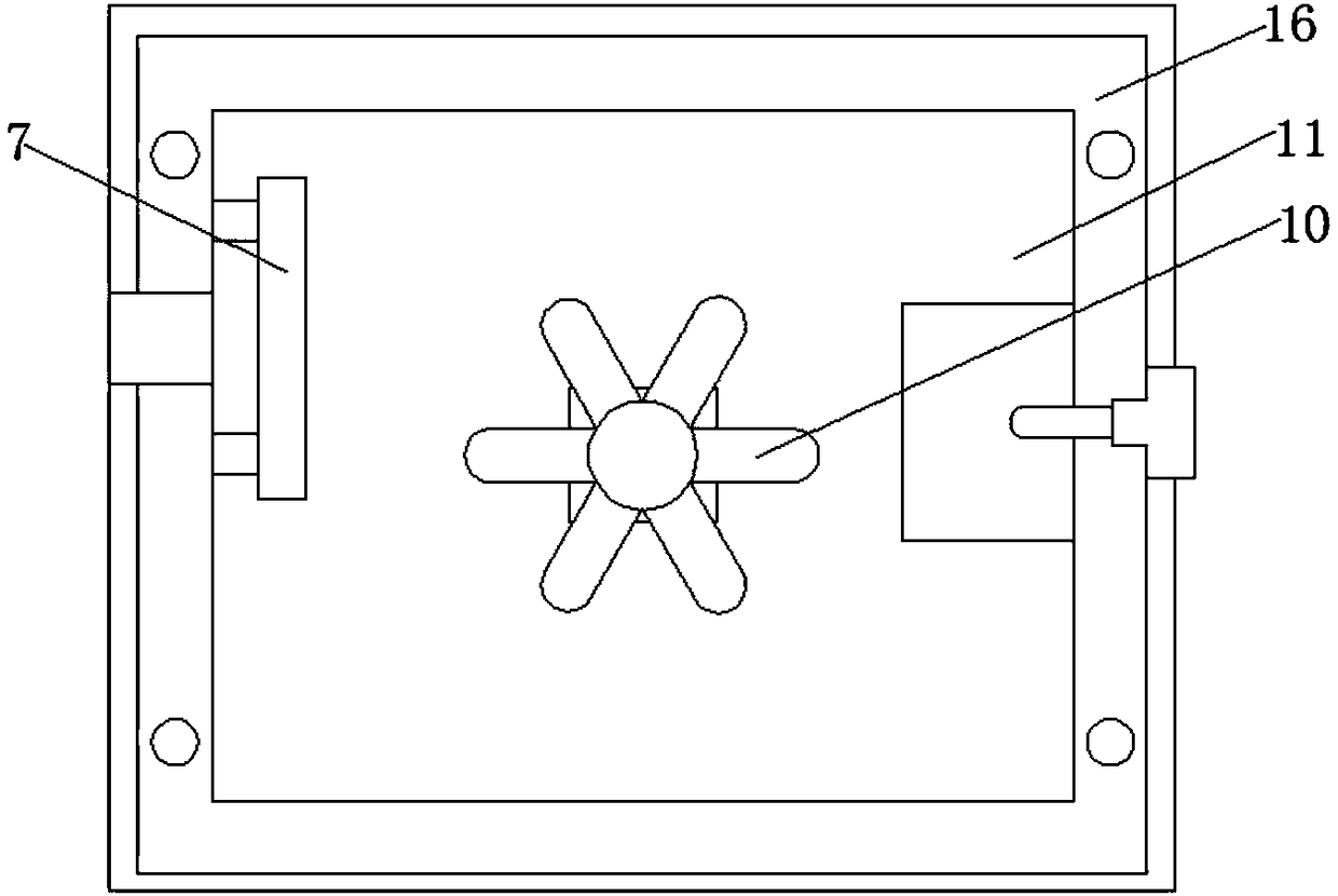
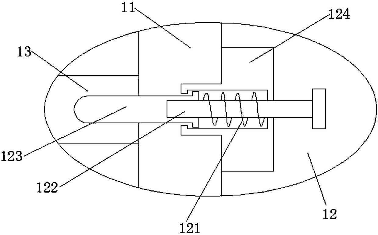
[0019] Example 2: Reference Figure 1-3 , a waste heat recovery device for cooling industrial oil, when the filter box 11 and the adsorption net 14 in the filter box 11 need to be disassembled and cleaned, the sealing cover 16, the motor 9 and the stirring paddle 10 need to be removed from the filter box 11 first. Since the filter screen 7 is clamped in the filter box 11, it can be quickly disassembled, and then manually pull the stretching rod 122, because the stretching rod 122 is threaded into the limit rod 123, so the movement of Detach the compression spring 121 of the driving limit rod 123 from the connecting plate 13, and then manually take out the guide plate, auxiliary rod, adsorption net 14 and connecting plate 13 from the filter box 11, which improves the protection of the filter screen 7, the adsorption net 14 and the connection plate 13. The cleaning of the filter box 11 is convenient and quick.


PUM


Abstract

The invention discloses a waste-heat recycling device for cooling industrial oil. The waste-heat recycling device comprises a cooling box and a filtering box, a fixed plate is fixedly placed in the cooling box, a cooling water pipe is connected in the fixed plate in a clamped manner, a flow pipe is mounted in the cooling water pipe, the inlet end of the flow pipe extends to the outer upper side ofthe cooling box, the outlet end of the flow pipe extends to the outer side of the cooling box and is connected with a conveying pipe, a liquid inlet hole is formed in the side wall of one end of thefiltering box, one end of the conveying pipe fixedly extends to the inside of the liquid inlet hole, a filtering screen is connected with the side wall, closes to the liquid inlet hole, of the filtering box in a clamped manner, and an adsorption screen is arranged in the filtering box. The waste-heat recycling rate in the industrial oil cooling process is increased, environmental pollution causedby direct emission of cooling waste heat is avoided, environments are protected, the cooling and filtering efficiency of the industrial oil is improved, and the production quality of the industrial oil is improved.

Description

technical field [0001] The invention relates to the technical field of industrial oil, in particular to a waste heat recovery device for cooling industrial oil. Background technique [0002] In the process of industrial oil processing, it is necessary to carry out cooling treatment. The general treatment method is to directly blow air through a high-power fan to improve the heat exchange efficiency. This method not only reduces the working efficiency of industrial oil processing, but also reduces the It greatly wastes the customer's time and cost. At the same time, a large amount of waste heat is generated in the cooling treatment of industrial oil, which often produces a large amount of waste heat. If this waste heat is directly discharged into the environment, it is likely to cause damage to the environment. At the same time, it will inevitably cause a lot of waste of energy. At the same time, the residual mechanical impurities, ash and carbon residue in the industrial oil...

Claims


Application Information

Patent Timeline
Patent Type & Authority Applications(China)
IPC IPC(8): F28D7/00H02N11/00B01D36/00
CPCF28D7/0008B01D36/00H02N11/00
Inventor 吴超
Owner 吴超
Why Eureka
Try Eureka