
Ultrathin direct type backlight module

A backlight module and direct-type technology, which is applied in optics, nonlinear optics, instruments, etc., can solve the problems of backlight module and display such as large thickness, heat accumulation, and restricted development, so as to improve the utilization rate of light energy and uniform illuminance performance, reduce the difficulty of processing and installation, and reduce the effect of light mixing distance

Active Publication Date: 2018-09-21
ANHUI NORMAL UNIV
View PDF5 Cites 9 Cited by
  • Summary
  • Abstract
  • Description
  • Claims
  • Application Information

AI Technical Summary

Problems solved by technology

[0004] However, the direct-type backlight module has disadvantages: In order to meet the uniformity requirements of the national standard, a certain light mixing distance is required between the liquid crystal panel and the light source, resulting in a large thickness of the backlight module and the display, which limits its development and does not meet the requirements. Nowadays people's demand for light, thin and beautiful
In order to improve the uniformity, reduce the thickness of the display and the light mixing distance, in the disclosed direct type LED backlight module technology, one type is to use a large number of low-power LEDs evenly arranged on the bottom plate, but the densely arranged LEDs will Causes heat buildup, poor heat dissipation, complex control circuits and increased cost
The other is to use a combination of free-form surface lenses and high-power LEDs to achieve ultra-thin and uniform lighting, but the lens design is complex, the production cost is high, the processing and assembly processes are complicated, and the light energy loss is large
[0005] The current direct-type LED backlight module mainly has the following disadvantages: the thickness of the module is large, the number of LED lamp beads is large, the design of the free-form surface lens is complicated, and the cost is high

Method used


Image

  • Ultrathin direct type backlight module
  • Ultrathin direct type backlight module
  • Ultrathin direct type backlight module

Examples


Embodiment Construction

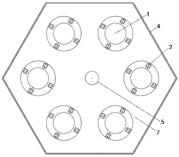
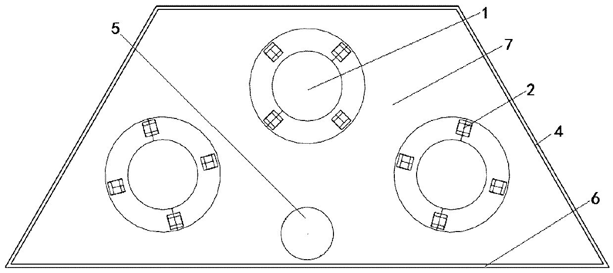
[0023] The application will be further described in detail below with reference to the accompanying drawings: an ultra-thin direct-lit backlight module, including multiple round tables, multi-section reflective partitions, LED lamp beads, cones, a bottom plate, and a frame.

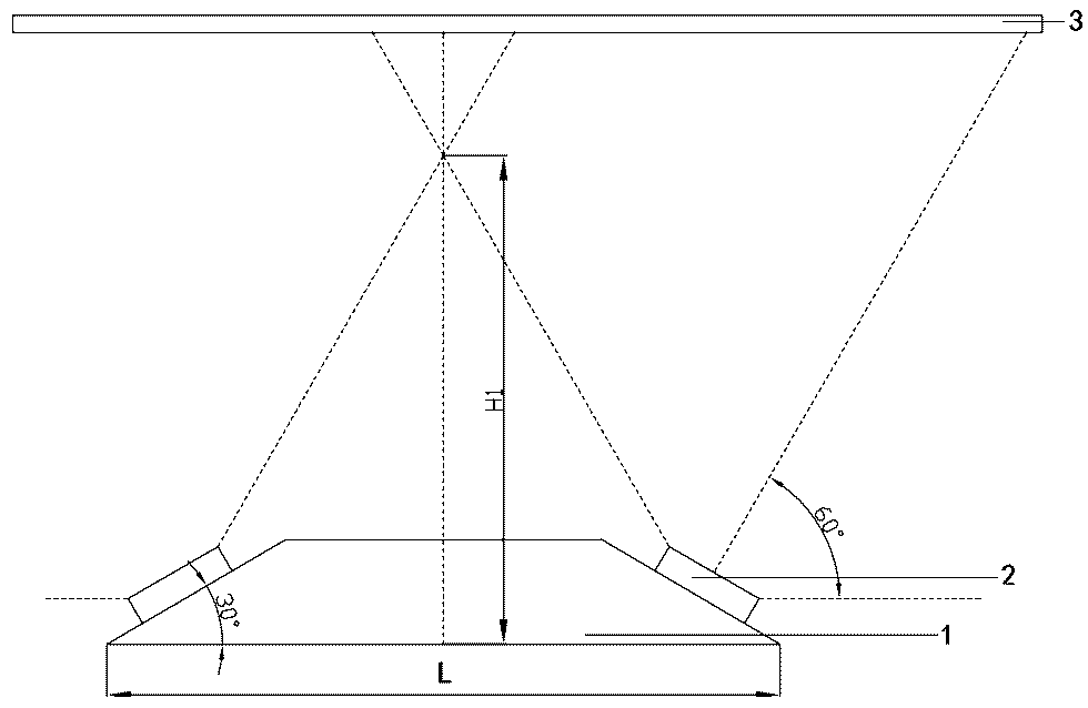
[0024] The size of the round platform used in the embodiment is: the diameter L of the bottom surface is 17.32mm, the inclination angle is 30°, and at least LED lamp beads can be placed on the side, such as figure 1 ; Due to the precise design of the size of the round table, the LED lamp beads are placed on the side of the round table, changing the outgoing direction of the light at the center of the maximum light intensity. The light mixing distance reduces the thickness of the liquid crystal display.

[0025] The LED lamp beads used in this example are produced by CREE Company, the model is XLamp XQ-A, and the bottom surface size is 1.6 1.6mm, the luminous flux of a single LED is 89 lm. Evenly place ...


PUM


Abstract

The invention discloses an ultrathin direct type backlight module which comprises a plurality of circular truncated cones, a plurality of sections of reflection partition plates, LED lamp beads, a circular cone, a base plate and a frame; the circular truncated cones, the circular cone and the reflection partition plates are all arranged on the base plate, and the base plate and the surface of theframe are both reflectors; the LED lamp beads are placed on the side faces of the circular truncated cones, the inclination angles of the circular truncated cones and the diameter of the bottom face are changed, the direction of the high light intensity of an LED chip is regulated, the light uniform difficulty is lowered, light is distributed again through the structures such as the circular truncated cones, the circular cones and the reflection partition plates, the light energy utilization rate and the brightness uniformity are improved, and the light mixing height is lowered. The thicknessof a liquid crystal display is lowered, no optical lens is needed, and therefore the machining and installing difficulty are lowered, and the cost is saved.

Description

technical field [0001] The application relates to the field of liquid crystal display, especially the ultra-thin direct-lit backlight module adopting round table and LED. Background technique [0002] A liquid crystal display (LCD) consists of a liquid crystal panel and a backlight module. Liquid crystal is a passive light-emitting display device, and it is often necessary to arrange a light source on the back of the liquid crystal. The liquid crystal panel displays images with different brightness by controlling the transmittance of light. The backlight module contains multiple light sources and optical components. The backlight module provides uniform light for the LCD panel. Its luminous performance will directly affect the display effect of the LCD. Usually the backlight module contains LED light sources. [0003] According to the distribution positions of the light sources in the backlight module, there are two types of backlight modules: a direct-type backlight module...

Claims


Application Information

Patent Timeline
Patent Type & Authority Applications(China)
IPC IPC(8): G02F1/13357
CPCG02F1/133603G02F1/133605G02F1/133611
Inventor 王先盛朱向冰李鹏飞陈瑾
Owner ANHUI NORMAL UNIV
Learn More