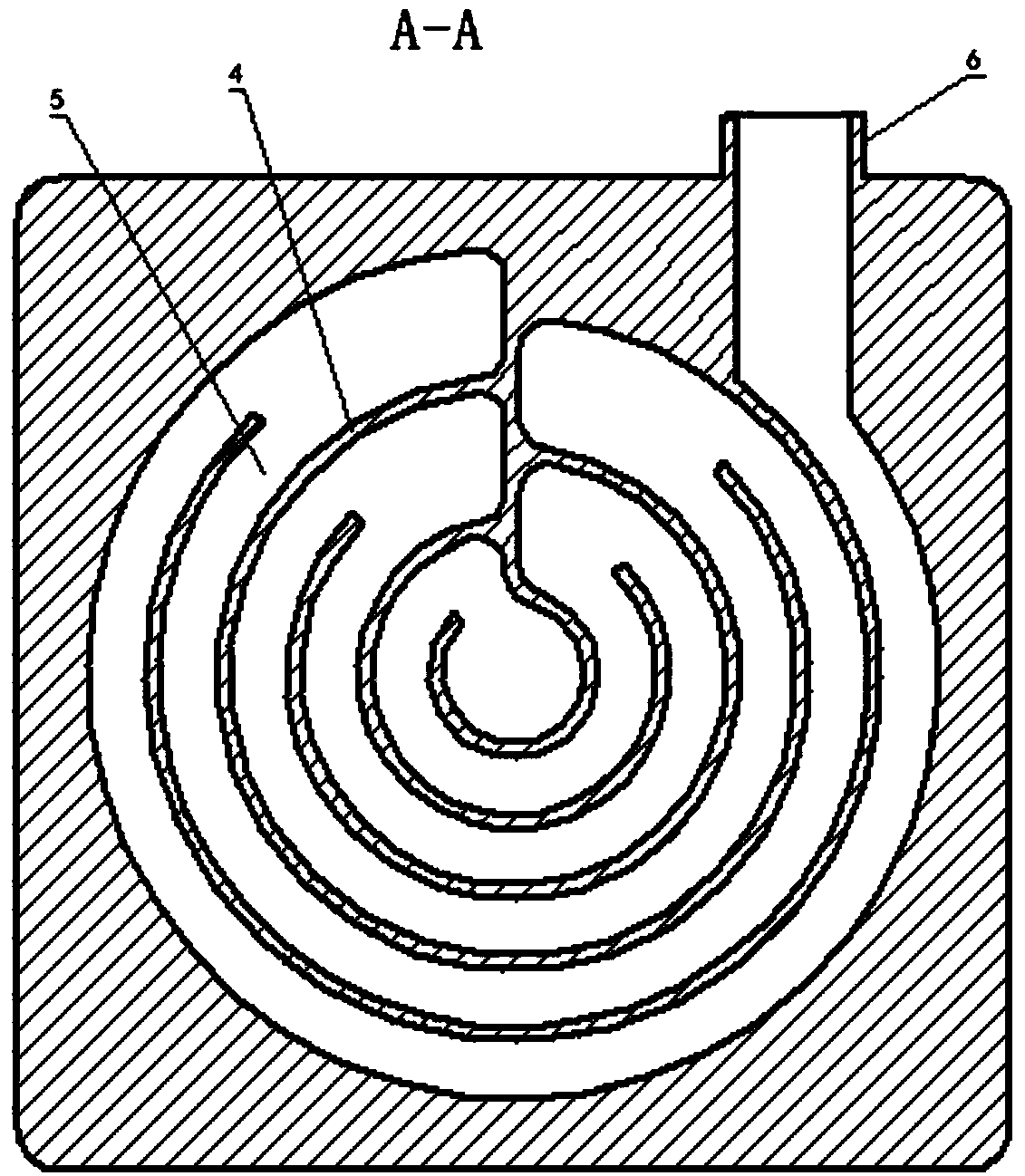
CPU radiator

A heat sink and main body technology, applied in the direction of instruments, electrical digital data processing, digital data processing components, etc., can solve the problems of large flow resistance, poor flow heat transfer capacity, high temperature, etc., to enhance convective heat transfer capacity, improve Heat exchange effect, effect of reducing flow resistance

Inactive Publication Date: 2018-09-21
ZHENGZHOU YUNHAI INFORMATION TECH CO LTD
View PDF4 Cites 0 Cited by
  • Summary
  • Abstract
  • Description
  • Claims
  • Application Information

AI Technical Summary

Problems solved by technology

Conventional air-cooled heat dissipation technology is relatively mature, but the sharp increase in fan energy consumption and noise problems caused by high heat flux chip air-cooled heat dissipation have seriously hindered the improvement of computer performance.
[0003] At present, many radiators adopt an in-and-out structure in which fluid enters from one end of the radiator and flows out from the other end, resulting in better heat dissipation near the inlet of the cooling fluid, and poor heat dissipation at the outlet. The overall performance is poor convective heat transfer capacity and large flow resistance.
The existing radiator has poor convective heat transfer capability, and local high temperature is prone to occur, which affects the performance of the equipment

Method used


Image

  • CPU radiator
  • CPU radiator

Examples


Embodiment Construction

[0017] In order to clearly illustrate the technical features of the present solution, the present invention will be described in detail below through specific implementation methods and in conjunction with the accompanying drawings. The following disclosure provides many different embodiments or examples for implementing different structures of the present invention. To simplify the disclosure of the present invention, components and arrangements of specific examples are described below. Furthermore, the present invention may repeat reference numerals and / or letters in different instances. This repetition is for the purpose of simplicity and clarity and does not in itself indicate a relationship between the various embodiments and / or arrangements discussed. It should be noted that components illustrated in the figures are not necessarily drawn to scale. Descriptions of well-known components and processing techniques and processes are omitted herein to avoid unnecessarily lim...


PUM


Abstract

The invention discloses a CPU radiator. The CPU radiator comprises a cover plate and a main body. The top end of the main body is opened. The cover plate is installed at an opening of the top end of the main body. The cover plate is adhered to the main body and sealed. Separating walls are installed in the main body. A water channel is formed between the separating walls. The water channel is divided into multiple circles, and the water channel is annular. One end of the water channel is positioned at the center of the main body, and the other end is positioned at the side face of the main body. Two ends of the water channel are a water inlet and a water outlet respectively. The CPU radiator is capable of radiating by using water with a larger specific heat capacity, and an annular radiating waterway can contact with a heat source better, thereby reducing a flow resistance, and avoiding a local high-temperature phenomenon.

Description

technical field [0001] The invention relates to the technical field of cooling equipment, in particular to a CPU radiator. Background technique [0002] With the continuous improvement of computing performance, the energy consumption and heat generated by the central processing unit (CPU) chip are also increasing, and the heat dissipation of the chip has become the most concerned issue in the large-scale or supercomputer industry today. Conventional air-cooled heat dissipation technology is relatively mature, but the sharp increase in fan energy consumption and noise problems caused by high heat flux chip air-cooled heat dissipation have seriously hindered the improvement of computer performance. [0003] At present, many radiators adopt an in-and-out structure in which fluid enters from one end of the radiator and flows out from the other end, resulting in better heat dissipation near the inlet of the cooling fluid, and poor heat dissipation at the outlet. The overall perfo...

Claims


Application Information

Patent Timeline
Patent Type & Authority Applications(China)
IPC IPC(8): G06F1/20
CPCG06F1/20
Inventor 张文昌
Owner ZHENGZHOU YUNHAI INFORMATION TECH CO LTD
Why Eureka
Try Eureka