Underwater image color compensation method based on electromagnetic theory

An underwater image and color compensation technology, applied in the field of image restoration, can solve problems such as poor image restoration quality

Inactive Publication Date: 2018-09-21
CHANGCHUN UNIV OF SCI & TECH
View PDF4 Cites 13 Cited by
  • Summary
  • Abstract
  • Description
  • Claims
  • Application Information

AI Technical Summary

Problems solved by technology

[0025] The present invention aims at the technical defects of the prior art, and provides an underwater image color compensation method based on the electromagnetic theory, so as to solve the technical problem of poor image restoration quality by conventional methods in the prior art
[0026] Another technical problem to be solved by the present invention is how to improve image contrast, clarity, and improve color distortion in the underwater image restoration process.

Method used


Image

  • Underwater image color compensation method based on electromagnetic theory
  • Underwater image color compensation method based on electromagnetic theory
  • Underwater image color compensation method based on electromagnetic theory

Examples


Embodiment 1

[0062] Embodiment 1 (improved dark channel prior and electromagnetic theory underwater image restoration)

[0063] 1. DCP theory

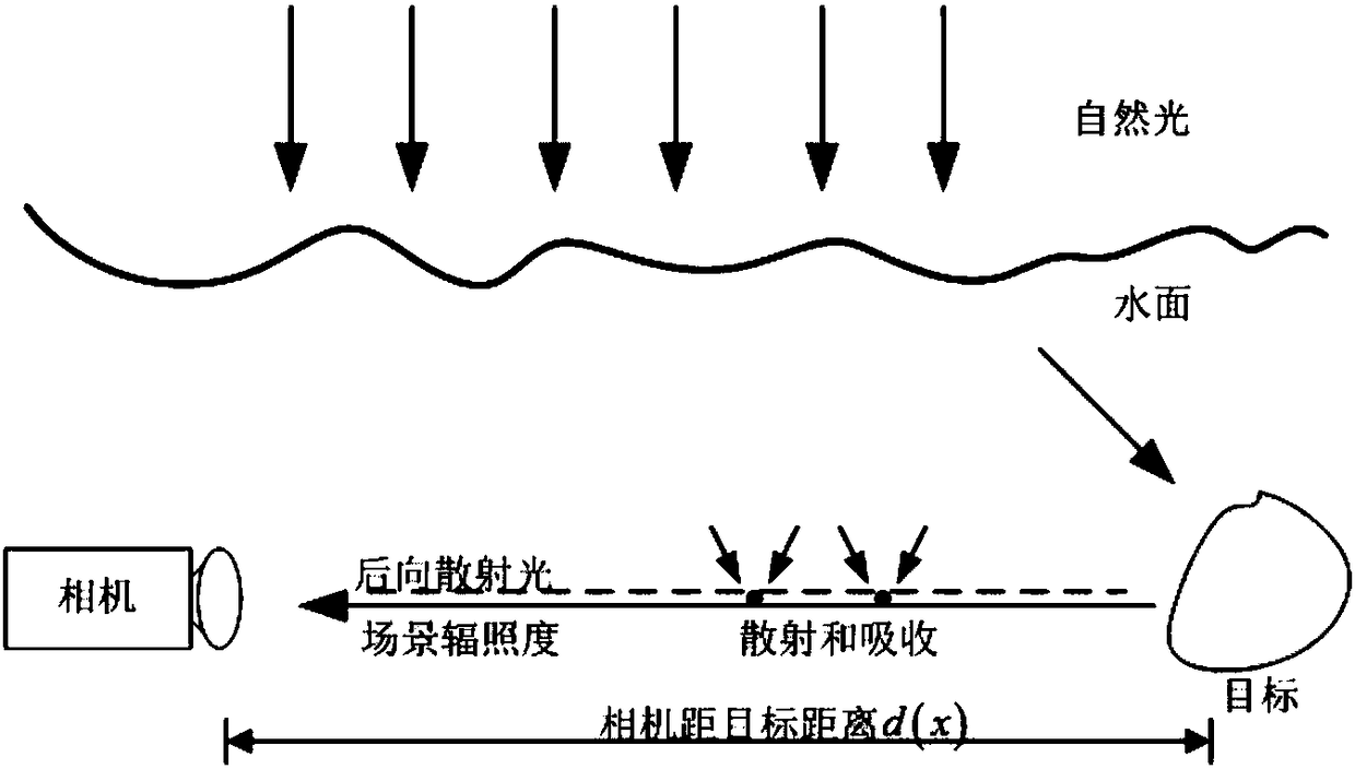
[0064] McCarney constructs the atmospheric scattering model of light waves under foggy conditions:

[0065] I(x)=J(x)t(x)+A[1-t(x)] (7)

[0066] Among them, I(x) represents the image captured by the camera, J(x) represents the reflected light of the object, which is the required fog-free image, A represents the atmospheric light intensity, t(x) represents the transmission coefficient of light waves in the atmosphere, and represents the reflection of the object The degree of light attenuation by the atmosphere, J(x)t(x) represents the light intensity after light attenuation containing object information, and A[1-t(x)] represents the atmospheric light intensity received by the camera. Equation (7) reveals the reasons for image quality degradation in foggy days. Image dehazing is equivalent to solving J(x) from Equation (7) to obtain a clear image. ...

Embodiment 2

[0121] This embodiment is used to investigate the actual effect of the method in Embodiment 1 on underwater image restoration.

[0122] In order to verify the effectiveness of the method of the present invention, multiple images in different environments were selected for experiments, and compared with the original images and images processed by the other two methods disclosed in the literature. Experimental results such as Figure 4~6 shown. From the experimental results, it can be seen that in different underwater environments, the group b method directly applies the dark channel prior theory to underwater image processing, ignoring the attenuation of light due to the absorption of water, and cannot correctly estimate the underwater environment. background light and transmittance, resulting in inconspicuous processing effects. Although the group c method takes into account the attenuation of light due to the absorption of water, it does not correctly estimate the transmis...


PUM


Abstract

The invention provides an underwater image color compensation method based on the electromagnetic theory and belongs to the technical field of image restoration. According to the technical scheme, anunderwater optical imaging model is established according to the propagation characteristics of light in water, and the absorption of light of a red band is absorbed by water to seriously cause R channel brightness attenuation of an image. The distance between a scene and a camera and the attenuation coefficient of an R channel caused by water absorption are obtained according to the electromagnetic wave transmission theory, and the transmission coefficient of the R channel is finally obtained. According to the method, the background light and the transmission coefficient of each channel can be effectively estimated, and the color of the image is compensated. Experimental results show that the image contrast and sharpness can be effectively improved and color distortion can be improved inthe invention compared with a traditional underwater image restoration algorithm.

Description

technical field [0001] The invention relates to the technical field of image restoration, in particular to an underwater image color compensation method based on electromagnetic theory. Background technique [0002] Underwater imaging is an important research direction of underwater optics and ocean optics. It is an important means and tool for human beings to detect and develop the ocean. effect. The underwater imaging environment is much more complicated than that in the air. In addition to the water body absorbing and scattering light, the suspended particles and plankton in the water will also absorb and scatter it. In addition, water absorbs light differently in different bands. Compared with imaging in air, underwater imaging not only contains noise and distortion, but also has problems such as low contrast, blur, and loss of color information, which seriously affects the imaging quality. . [0003] As light travels underwater, its loss varies with wavelength. The ...

Claims


Application Information

Patent Timeline
Patent Type & Authority Applications(China)
IPC IPC(8): G06T5/00G06T7/90
CPCG06T5/001G06T5/003G06T7/90
Inventor 朴燕蒋泽新孙荣春王宇臧景峰张竟秋
Owner CHANGCHUN UNIV OF SCI & TECH
Why Eureka
Try Eureka