Active optical positioning method, device and system

An optical positioning and active technology, applied in the field of computer vision, can solve problems such as limited working distance, harsh camera installation configuration, and poor robustness, and achieve the effect of large working distance, reduced complexity, and improved robustness

Inactive Publication Date: 2018-09-21
北京轻威科技有限责任公司
View PDF4 Cites 6 Cited by
  • Summary
  • Abstract
  • Description
  • Claims
  • Application Information

AI Technical Summary

Problems solved by technology

The disadvantages of this solution are obvious: the cameras should be prevented from directly illuminating each other to avoid mutual interference of infrared light, so the installation and configuration of the cameras are strict; the smooth surface can easily reflect infrared light, so more interference points are likely to occur in the scene Poor performance; passive light is restricted by reflection, and the working distance is limited (for example, no more than 5 meters)

Method used


Image

  • Active optical positioning method, device and system
  • Active optical positioning method, device and system
  • Active optical positioning method, device and system

Examples


Embodiment Construction

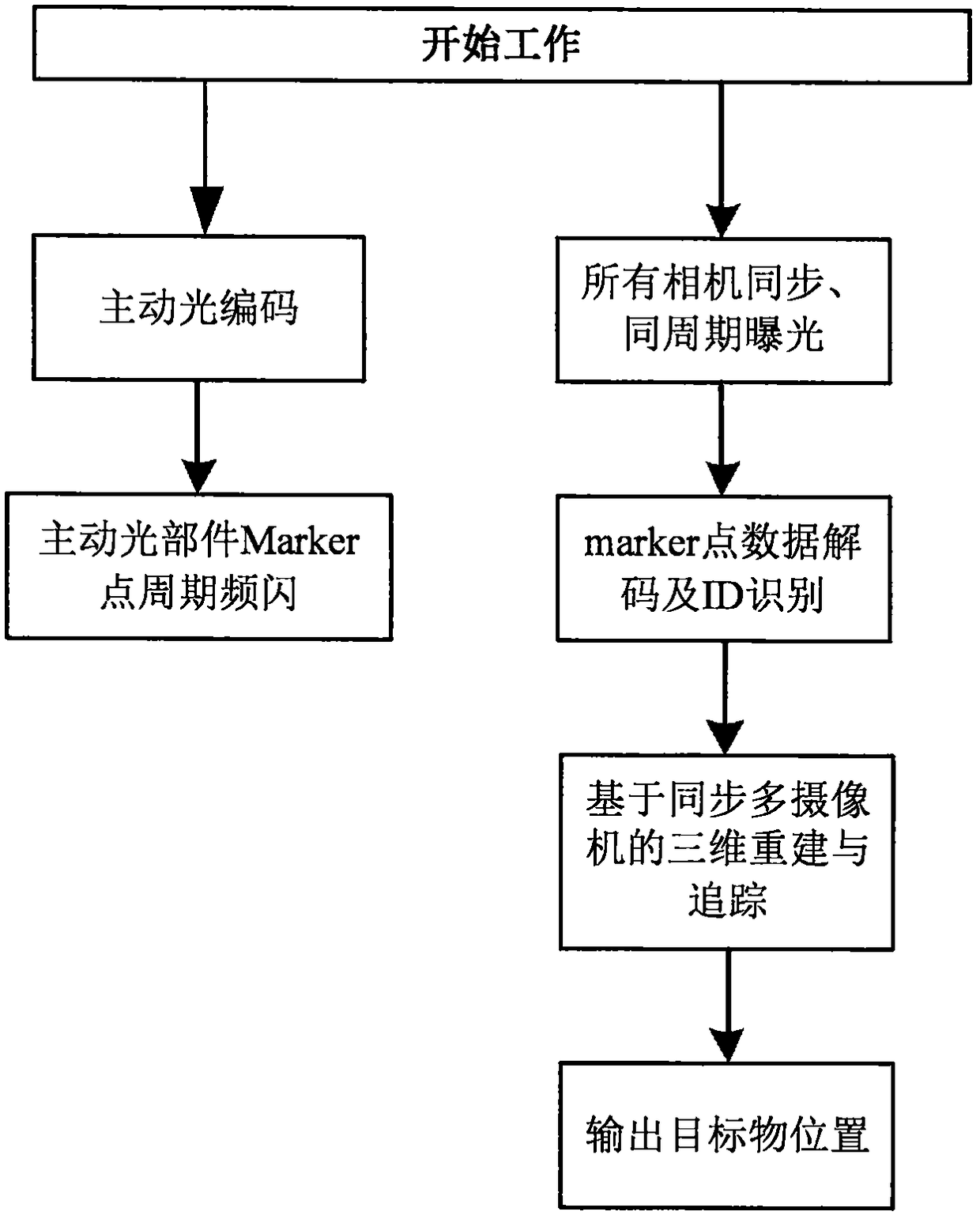
[0027] The content of the present invention will be further described below in conjunction with the accompanying drawings.

[0028] like Figure 4 As shown, a schematic diagram of an active optical positioning system according to the present invention. A plurality of infrared cameras are arranged in the positioning space, respectively arranged in different positions of the positioning space, so as to ensure that the irradiation range of the infrared cameras can cover the entire positioning space. The calculation unit (that is, the upper computer) communicates with the infrared camera through a wired method, and communicates with the Tracker through a wireless method. The upper computer sends synchronization information to the camera and Tracker through the communication module to realize system synchronization.

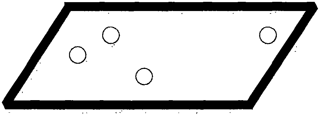
[0029] like figure 2 As shown, the Tracker, an active optical positioning device according to the present invention, is characterized in that the surface of the T...


PUM


Abstract

The invention relates to a multi-camera internal and external parameter calibration method, device and system based on a single-point calibration object. Specifically, the method is characterized in that, in any positioning space, infrared cameras are distributed according to actual requirements of the positioning space; an object wears a Tracker; LED marker points, which can be coded and can emitinfrared light, are attached on the surface of the Tracker; the system controls camera exposure and LED marker flicker synchronization through a wireless and wired communication mode; image information of the positioning space is obtained in real time through the infrared cameras; codes of the Marker points are identified according to the image information and space location information of the marker points is obtained; and space location information of the Tracker, that is, the space location information of the object, is calculated according to the space location information of the marker points, thereby realizing real-time location tracking of the object. The beneficial effects are that, through the active optical positioning technology, the method is higher in anti-interference performance than a passive optical positioning scheme and is better in robustness, and can be pushed to outdoor scenes; and in the active optical positioning scheme, working distance of cameras is large, sothat the number of the cameras to be installed per unit area is small, and cost is greatly reduced.

Description

technical field [0001] The invention relates to the field of computer vision, in particular to an active optical positioning method, device and system Background technique [0002] Camera calibration technology uses the 2D image of the calibrated object to recover the internal and external parameters of the camera, and then reconstructs the 3D information of the scene. It is a key step in the field of computer vision and has wide applications in industry, aerospace, cultural creativity and other fields. In recent years, with the vigorous development of virtual reality, the perspective of a single camera cannot meet people's expectations for a large-scale three-dimensional space, and multi-camera combination and calibration have gradually become a new research hotspot. However, the existing multi-camera calibration methods often require the calibration object to move in the common field of view of all cameras at the same time, which increases the difficulty of actual operatio...

Claims


Application Information

Patent Timeline
Patent Type & Authority Applications(China)
IPC IPC(8): G06T7/70G06T7/80
CPCG06T7/70G06T7/80
Inventor 黄永鑫
Owner 北京轻威科技有限责任公司
Why Eureka
Try Eureka