Synchronous rectifier control circuit

A technology of synchronous rectification and control circuit, which is applied in the direction of electrical components, high-efficiency power electronic conversion, conversion of AC power input to DC power output, etc. It can solve the problems of low power consumption and high reliability of the circuit, and reduce power consumption and save energy. , the effect of improving the overall efficiency

Inactive Publication Date: 2018-09-21
UNIV OF ELECTRONICS SCI & TECH OF CHINA
View PDF10 Cites 8 Cited by
  • Summary
  • Abstract
  • Description
  • Claims
  • Application Information

AI Technical Summary

Problems solved by technology

[0005] The purpose of the present invention is to propose a control circuit for controlling the rectification circuit of motor power generation in view of the technical difficulty and cost problems existing in the current synchronous rectification technology, with simple structure, low circuit power consumption and high reliability

Method used


Image

  • Synchronous rectifier control circuit
  • Synchronous rectifier control circuit
  • Synchronous rectifier control circuit

Examples


Embodiment Construction

[0026] The technical solution of the present invention will be described in detail below in conjunction with the accompanying drawings and specific embodiments.

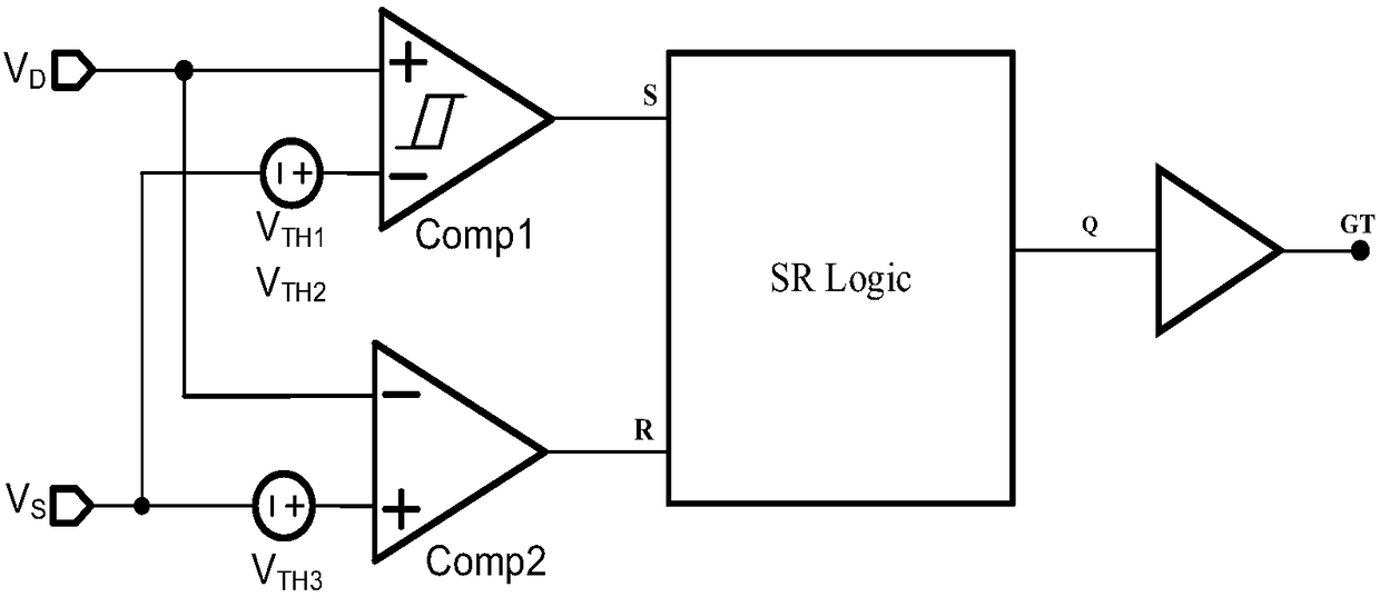
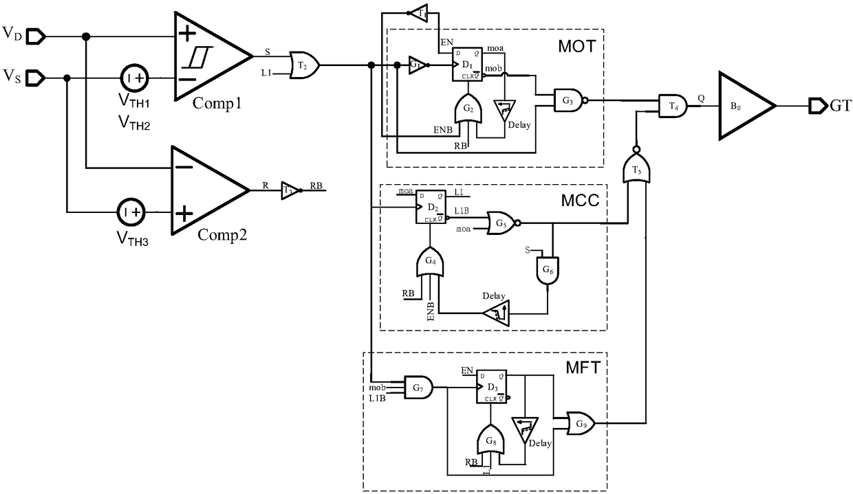
[0027]A synchronous rectification control circuit proposed by the present invention turns on and off the rectifier by detecting the drain-source pressure difference of the rectifier (ie power MOSFET) in the synchronous rectifier circuit. Such as figure 1 As shown, it includes voltage detection module, synchronous rectification logic control module and drive module. Control the minimum on-time of the power MOSFET to avoid oscillation after turning on the power MOSFET, and the drive module is used to provide gate drive.

[0028] Such as figure 1 and figure 2 Shown is an implementation circuit form of the voltage detection module, the voltage detection module is used to detect the drain-source voltage of the rectifier and generate the first detection signal and the second detection signal, including the first compar...


PUM


Abstract

The invention relates to a synchronous rectifier control circuit and belongs to an electronic circuit technology. A rectifier tube is turned on and off through detecting the leakage source pressure difference of the rectifier tube; the synchronous rectifier control circuit comprises a voltage detection module, a synchronous rectifier logic control module and a drive module; the voltage detection module is used for detecting the leakage source pressure difference of the rectifier tube; the synchronous rectifier logic control module is used for controlling the minimum conduction time of the rectifier tube and avoiding the oscillation after the rectifier tube is turned on; the drive module is used for providing grid electrode drive. The synchronous rectifier control circuit provided by the invention has the benefits that a drive mode is simple and reliable; the power consumption of the rectifier can be greatly reduced, the temperature of a rectifier bridge is reduced, and the system reliability is improved; meanwhile, the lower conduction loss can be realized, the overall efficiency of a power generator is improved, and the effects of energy conservation, cleanness and environmental protection are realized.

Description

technical field [0001] The invention belongs to the electronic circuit technology, and in particular relates to a control circuit for a rectifier circuit used for electric motor power generation. Background technique [0002] At present, the generator rectifier mainly uses silicon diodes as rectification elements. The forward voltage drop of silicon diodes is about 0.3-1V, and the on-state power consumption is very large when the current is high. With the popularization of automobiles, the power consumption caused by silicon diode rectification cannot be ignored. [0003] Synchronous rectification technology (Synchronous Rectification, SR) uses a low-voltage power metal-oxide semiconductor field effect transistor (Power MOSFET) as a rectifier device, and its channel on-state resistance can be used to reduce the overall power consumption of the rectifier module. The main difficulty in adopting synchronous rectification technology lies in the gate control of its rectifier tub...

Claims


Application Information

Patent Timeline
Patent Type & Authority Applications(China)
IPC IPC(8): H02M7/217
CPCH02M7/217H02M1/0054Y02B70/10
Inventor 李泽宏熊涵风罗仕麟张成发赵念
Owner UNIV OF ELECTRONICS SCI & TECH OF CHINA
Why Eureka
Try Eureka