Dust collector side air inlet device and bag dust collector
A technology of side air intake and dust collector, which is applied in chemical instruments and methods, separation of dispersed particles, filtration of dispersed particles, etc. It can solve the problems of dust particle erosion, dust collector directly connected to the air inlet, and uneven distribution of air inlet airflow. , to achieve the effects of reduced operating costs, simple structure, and small resistance loss
- Summary
- Abstract
- Description
- Claims
- Application Information
AI Technical Summary
Problems solved by technology
Method used
Image

Examples
Embodiment Construction
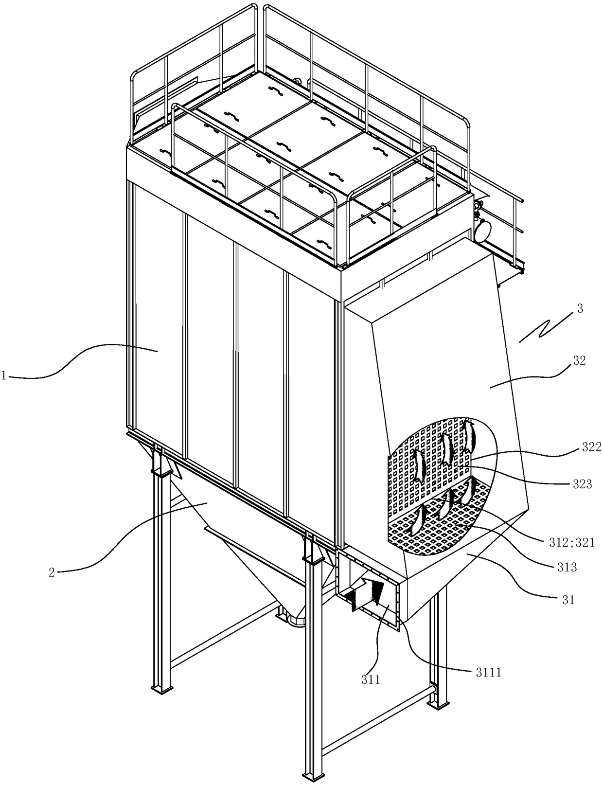
[0021] refer to figure 1 and figure 2 As shown, a bag filter includes a dust removal chamber 1, a dust collection chamber 2 and a side air inlet device 3.
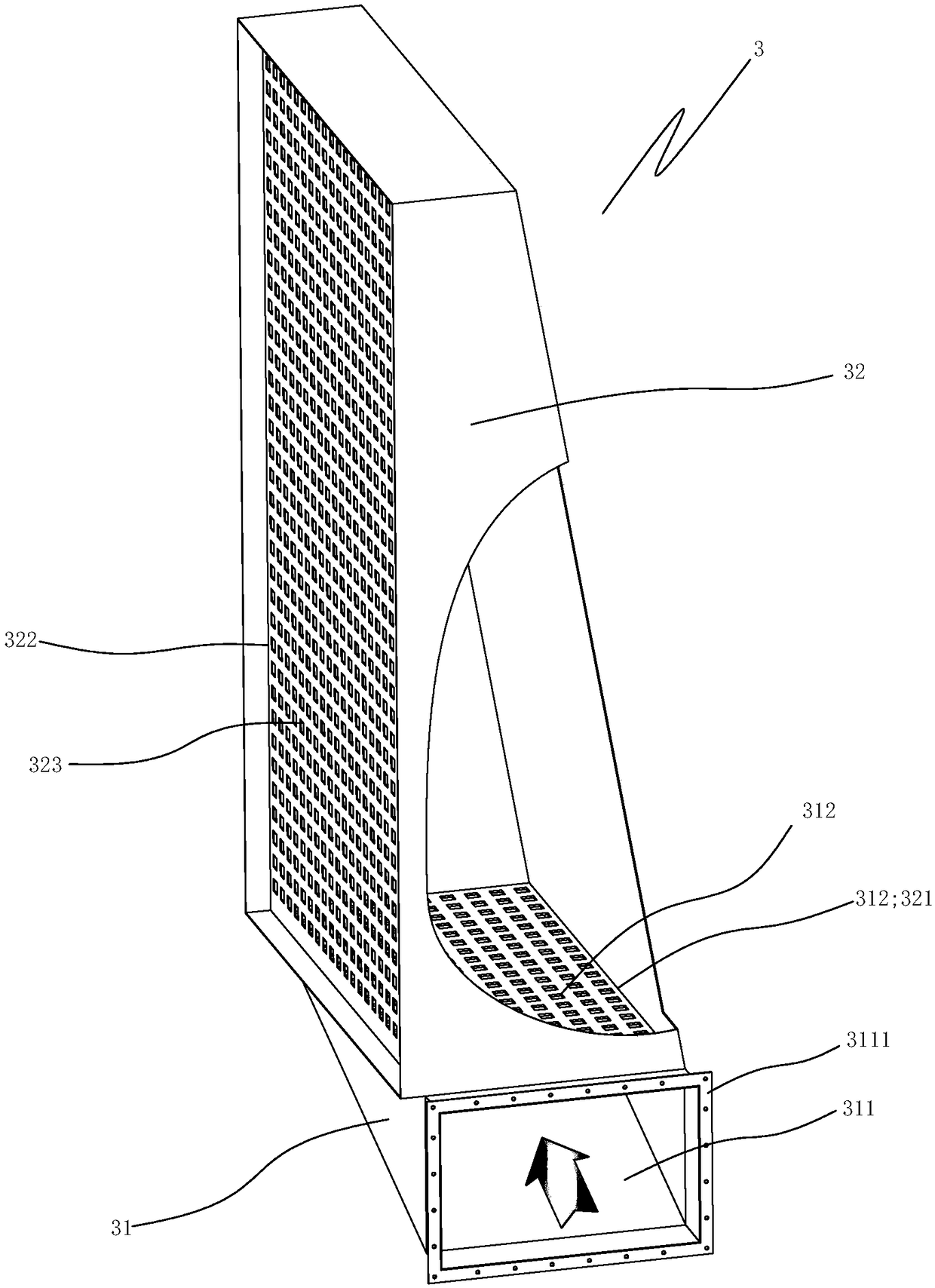
[0022] The side air intake device 3 includes a first airflow diffusion chamber 31 and a second airflow diffusion chamber 32, the first airflow diffusion chamber 31 is provided with a first air inlet 311 and a first air outlet 312, and the second airflow diffusion chamber 32 is provided with a second The air inlet 321 and the second air outlet 322, the first air inlet 311 is provided with a flange 3111 for connecting the tail gas flue, the first air outlet 312 and the second air inlet 321 are equal in size and docked with each other, the second air outlet 322 and The sides of the dust removal chamber 1 are butted, the first air outlet 312 is provided with a first porous air uniformity plate 313, the second air outlet 322 is provided with a second porous air uniformity plate 323,
[0023] The cross-section of the first ai...
PUM
 Abstract
Description
Claims
Application Information
 - R&D
- Intellectual Property
- Life Sciences
- Materials
- Tech Scout
- Unparalleled Data Quality
- Higher Quality Content
- 60% Fewer Hallucinations
Browse by: Latest US Patents, China's latest patents, Technical Efficacy Thesaurus, Application Domain, Technology Topic, Popular Technical Reports.
© 2025 PatSnap. All rights reserved.Legal|Privacy policy|Modern Slavery Act Transparency Statement|Sitemap|About US| Contact US: help@patsnap.com