Hydraulic refueling substation for gas-fueled vehicles and oil-returning and gas-releasing system thereof

A technology of gas filling sub-station and hydraulic sub-station, which is applied in pressure vessels, fixed-capacity gas storage tanks, gas processing/storage effects, etc., can solve the problems of high residual pressure, large gas loss, long unloading hose, etc. The effect of length reduction, gas loss reduction, and residual pressure reduction

Pending Publication Date: 2018-09-25
ENRIC (LANGFANG) ENERGY EQUIP INTEGRATION CO LTD +2
0 Cites 0 Cited by

AI-Extracted Technical Summary

Problems solved by technology

[0006] In order to solve the technical problems of high residual pressure and large gas loss caused by the excessively long unloading hose in the filling substation of hydraulic natural gas vehicles in the pr...

Method used

Compared with the way in the prior art that the unloading device 13 is integrated in the hydraulic sub-station, the unloading device of the present invention is independent from the hydraulic sub-station 12, becomes an independent equipment, and the unloading device is arranged Between the sub-station car 11 and the hydraulic sub-station 12. Thereby, the distance between the unloading device 13 and the sub-station car 14 is shortened, so that the length of the unloading hose 15 connecting the unloading device 13 and the sub-station car 14 is reduced, thereby reducing the residual pressure in the unloading hose and reducing the pressure. Minimize the residual gas in the unloading hose 15, that is, reduce gas loss.
Generally, in the sub-station car 11, 8 container tube bundles are included, and two groups of oil injection and return assemblies 132 carry out oil injection and oil return to different gas cylinders in the sub-station car 11 respectively, and one of them is injected back When the oil assembly 132 performs oil injection, another oil injection return assembly 132 performs oil return. For example, when the first oil return assembly 132 returns oil to the manifold bundle A, the second oil return assembly 132 injects oil to the manifold bundle B; when the second oil return assembly 132 returns the oil to the manifold bundle When B returns oil, the first oil injection assembly 132 injects oil into the manifold bundle C. Two groups of oil injection and return assemblies 132 perform oil injection and oil return alternately to improve the efficiency of oil injection and oil return.
The remote control module 131 is installed in the unloading device 13, and the unloading device 13 is arranged near the substation car 11, therefore, compared with the mode in which the control module is installed in the hydraulic substation in the prior art, the substation is reduced. The length ...

Abstract

The invention discloses a hydraulic refueling substation for gas-fueled vehicles and an oil-returning and gas-releasing system thereof. The oil-returning and gas-releasing system comprises a substation vehicle for transporting and storing compressed natural gas, a hydraulic substation for providing high-pressure liquid, and a gas-releasing device connected with the substation vehicle through an unloading hose and connected with the hydraulic substation through a steel pipe, wherein the gas-releasing device controls the unloading of the compressed natural gas in the substation vehicle in virtueof the high-pressure liquid provided by the hydraulic substation and controls the returning of the high-pressure liquid from the substation vehicle to the hydraulic substation after completion of theunloading, and the deaerator is independent of the substation vehicle and the hydraulic substation and located between the substation vehicle and the hydraulic substation. The hydraulic refueling substation for gas-fueled vehicles comprises the above oil-returning and gas-releasing system. The hydraulic refueling substation for gas-fueled vehicles and the oil-returning and gas-releasing system thereof in the invention reduce residual pressure in the unloading hose and lower gas loss.

Application Domain

Container filling methodsGas handling/storage effects +4

Technology Topic

Automotive engineeringHigh pressure +4

Image

  • Hydraulic refueling substation for gas-fueled vehicles and oil-returning and gas-releasing system thereof
  • Hydraulic refueling substation for gas-fueled vehicles and oil-returning and gas-releasing system thereof
  • Hydraulic refueling substation for gas-fueled vehicles and oil-returning and gas-releasing system thereof

Examples

  • Experimental program(1)

Example Embodiment

[0043] In order to further illustrate the principle and structure of the present invention, the preferred embodiments of the present invention will now be described in detail with reference to the accompanying drawings.
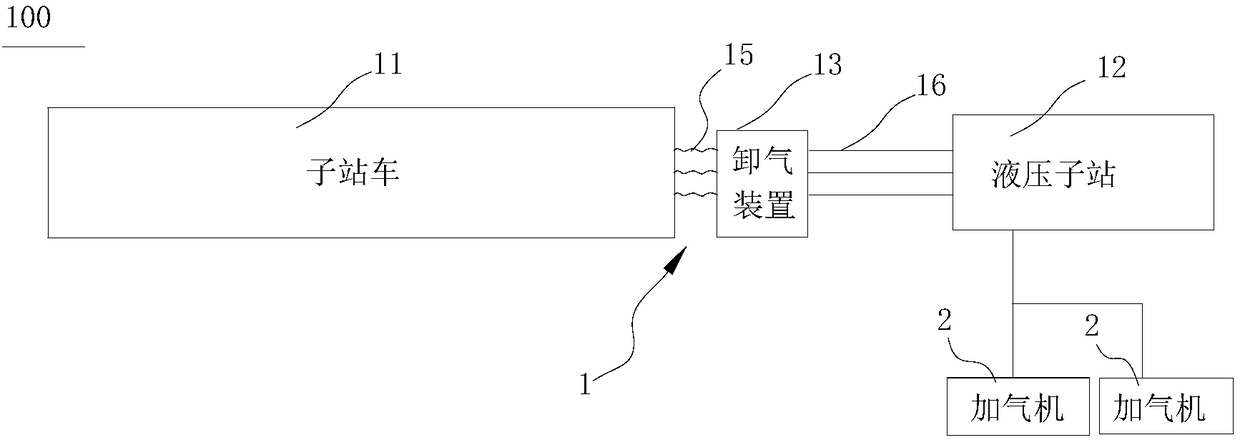
[0044] Such as figure 1 As shown, it is a block diagram of the hydraulic natural gas vehicle refueling substation of the present invention. The hydraulic natural gas vehicle refueling substation 100 includes an oil return and unloading system 1 and a refueling machine 2. The refueling machine 2 is connected to the gas storage tank of the oil return and unloading system 1 through a pipeline. The oil return and unloading system 1 is The gas machine 2 transports compressed natural gas, and the gas dispenser 2 injects the compressed natural gas into the gas cylinder of the automobile.
[0045] The oil return and gas unloading system 1 includes a substation car 11 (also called a substation trailer), a hydraulic substation 12 and an unloading device 13.
[0046] The substation car 11 includes a trailer and a plurality of container tube bundles fixed on the trailer, and the container tube bundle is used for storing compressed natural gas.
[0047] The hydraulic substation 12 includes a hydraulic substation skid, a liquid storage tank, and an air storage tank. The hydraulic sub-station skid includes hydraulic pressure boosting system, pneumatic control system, valves and pipelines, etc. The pneumatic control system and valves of the hydraulic sub-station 12 are integrated on the skid. The storage tank is used to store high-pressure liquids with special properties, such as hydraulic oil. The gas storage tank is used to temporarily store the compressed natural gas unloaded from the substation car 11.
[0048] The unloading device 13 is connected to the sub-station car 11 through the unloading hose 15 and is connected to the hydraulic sub-station 12 through the steel pipe 16. The unloading device 13 uses the high pressure liquid provided by the hydraulic substation 12 to control the unloading of the compressed natural gas in the substation vehicle 11. Specifically, the unloading device 13 controls the on and off of the pneumatic valves in the substation car 11 through its own remote control module (described in detail below), and fills the high-pressure liquid provided by the hydraulic substation 12 into the collection of the substation car 11 In the tube bundle, the high-pressure liquid pushes out the compressed natural gas in the tube bundle. After the unloading is completed, the unloading device 13 controls the unloaded high-pressure liquid to return from the substation car 11 to the hydraulic substation 12 again.
[0049] The air unloading device 13 is independent of the substation car 11 and the hydraulic substation 12 and is located between the substation car 11 and the hydraulic substation 12.
[0050] More preferably, the degassing device 13 is close to the substation car 11, that is, the distance between the degassing device 13 and the substation car 11 is smaller than the distance between the degassing device 13 and the hydraulic substation 12. Such as figure 1 As shown, the distance between the degassing device 13 and the substation car 11 is less than or equal to 5 meters, and the distance between the degassing device and the substation car 11 is greater than or equal to 20 meters.
[0051] Compared with the prior art method of integrating the degassing device 13 in the hydraulic substation, the degassing device of the present invention is separated from the hydraulic substation 12 and becomes an independent equipment, and the degassing device is placed in the substation. Between car 11 and hydraulic substation 12. Thereby, the distance between the unloading device 13 and the sub-station car 14 is reduced, so that the length of the unloading hose 15 connecting the unloading device 13 and the sub-station car 14 is reduced, thereby reducing the residual pressure in the unloading hose and reducing If the residual gas in the unloading hose 15 is small, the gas loss is reduced.
[0052] Further, such as figure 2 with image 3 As shown, figure 2 It is a schematic diagram of the structure of the degassing device of the present invention, image 3 It is the structure diagram of the remote control module of the unloading device. The degassing device 13 includes a remote control module 131, an oil-returning component 132 and a degassing component 133.
[0053] More preferably, the degassing device 13 further includes a cabinet 134, and the remote control module 131, the oil return component 132 and the degassing component 133 are all installed in the cabinet 134.
[0054] The remote control module 131 includes an explosion-proof junction box 1311, a control chip 1312 arranged in the explosion-proof junction box, an explosion-proof remote control valve 1313, and a pneumatic signal pipeline (not shown). The explosion-proof remote control valve 1313 is connected to the pneumatic valve of the substation vehicle 11 through a pneumatic signal pipeline. The control chip 1312 is electrically signal connected with the remote control system. The remote control system controls the on and off of the explosion-proof remote control valve 1313 through the control chip 1312, and then controls the on and off of the pneumatic valve of the substation car 11.
[0055] The remote control module 131 is installed in the degassing device 13, and the degassing device 13 is arranged close to the substation car 11. Therefore, compared with the prior art in which the control module is installed in the hydraulic substation, the substation car 11 is reduced. The length of the pneumatic signal pipeline connected between the pneumatic valve and the control module solves the problem that the pneumatic signal pipeline is too long in the prior art, which causes the long delay time of the pneumatic valve of the substation car 11 to close. That is to say, the air discharge device of the present invention can effectively avoid the problem of too slow response speed of the pneumatic valve of the substation car 11, and ensure the smooth operation of the hydraulic substation 12.
[0056] The cabinet 134 is provided with a plurality of interfaces 1341 for connecting the pneumatic signal pipelines of the substation car 11, and the pneumatic signal pipelines are connected to the explosion-proof remote control valve 1313 in the cabinet 134 through the interfaces 1341.
[0057] The unloading hose 15 includes a first unloading hose and a second unloading hose. The first unloading hose connects the oil return assembly 132 and the liquid inlet and outlet of the substation vehicle 11, and is used to transport liquid, that is, for oil filling or oil return; The second unloading hose is connected to the unloading assembly 133 and the unloading port of the substation car 11, and is used for conveying compressed gas, that is, for unloading.
[0058] in figure 2 There are two sets of oil-returning components 132, so there are two first unloading hoses, and the two first unloading hoses are respectively connected to the two groups of oil-returning components 132. Therefore, as figure 1 As shown, there are three unloading hoses 15, two of which are the first unloading hoses, and the two first unloading hoses are respectively connected to two sets of oil return assemblies 132, the other is the second unloading hose, the second unloading hose The hose is connected to the degassing assembly 133.
[0059] Similarly, the steel pipe 16 includes a first steel pipe and a second steel pipe. The first steel pipe is connected to the oil injection and return assembly 132 and the liquid storage tank of the hydraulic substation 12, and is used to transport liquid, that is, for oil injection or return. The gas unloading assembly 133 and the gas storage tank of the hydraulic sub-station 12 are used for conveying compressed gas, that is, for unloading.
[0060] in figure 2 There are two sets of oil-returning components 132, so there are two first steel pipes connected to the two sets of oil-returning components 132 respectively. Therefore, as figure 1 As shown, there are three steel pipes 16, two of which are the first steel pipes, and the two first steel pipes are respectively connected to two sets of oil-returning assemblies 132, the other is a second steel pipe, and the second steel pipe is connected to the degassing assembly 133.
[0061] Such as figure 2 As shown, the cabinet 134 is provided with two sets of adjacently arranged oil return assemblies 132. Each oil return assembly 132 includes an oil return detection member 1321, a block 1322 arranged outside the cabinet 134 The quick connector on 1322, the valve 1323 connected to the quick connector, and the pressure gauge 1325 connected to the quick connector. The oil return detection component 1321 is connected to the quick connector through a pipe 1324, whereby the oil return detection component 1321 is connected to the first unloading hose connecting the substation vehicle 11. The first steel pipe communicates with the lower liquid port of the oil return assembly 132.
[0062] Such as Figure 4 As shown, it is a schematic structural diagram of the oil return detection component of the present invention. The oil return detection component 1321 includes a detection tube 1321a, an upper flange cover 1321b, a lower flange cover 1321c, and a liquid detector. The liquid detector includes an upper liquid detector 1321d and a lower liquid detector 1321e. The valve 1323 is used to control whether the high-pressure liquid in the first unloading hose flows into the detection tube 1321a, and the pressure gauge 1325 is used to display the working pressure in the detection tube 1321a, which is convenient for the operator to observe in time.
[0063] The upper flange cover 1321b and the lower flange cover 1321c respectively seal the upper port and the lower port of the detection tube 1321a. The upper flange cover 1321b and the lower flange cover 1321c are respectively provided with an upper liquid port 1321f and a lower liquid port 1321g. The upper liquid port 1321f is in communication with the first unloading hose through a pipe 1324, and the pipe 1324 drains the liquid in the first unloading hose to the detection tube 1321a through a quick connector. The lower liquid port 1321g communicates with the first steel pipe through a pipe (not shown).
[0064] The upper liquid detector 1321d and the lower liquid detector 1321e are arranged inside the detection tube 1321 and are respectively close to the upper port and the lower port of the detection tube 1321a.
[0065] When the oil return and unloading system is filled with oil, the high-pressure liquid in the hydraulic substation 12 flows into the detection tube 1321a through the first steel pipe and the lower liquid port 1321g, and the high-pressure liquid in the detection tube 1321a passes through the upper liquid port 1321f and the first unloading vehicle The hose is injected into the collection tube bundle of the substation car 11 to be discharged.
[0066] When the oil return and unloading system performs oil return, the residual pressure of a small part of the compressed natural gas remaining in the substation car 11 and an appropriate elevation angle are used to transport the high-pressure liquid to the detection tube 1321a through the first unloading hose and the upper liquid port 1321f, After the high-pressure liquid passes through the detection tube 1321a, it returns to the hydraulic substation 12 through the lower liquid port 1321g and the first steel pipe.
[0067] During the oil return process, the upper liquid detector 1321d and the lower liquid detector 1321e work to detect whether the medium flowing through the detection tube is liquid or gas, and feedback the detection result to the remote control system.
[0068] More specifically, during the oil return process, when the upper liquid detector 1321d detects gas, the upper liquid detector 1321d sends the detection result to the remote control system, and the remote control system closes the oil return valve of the substation car 11 according to the detection result. , Suspend oil return. After closing the oil return valve of the substation car 11 for a period of time, for example, 5 seconds, a small part of the residual gas continues to flow to the bottom end of the detection tube 1321a, and the lower liquid detector 1321e arranged near the lower port of the detection tube 1321a detects After this period of time, whether the medium in the detection tube 1321a is still a gas, and the detection result is sent to the remote control system. The remote control system determines whether to continue to close the oil return valve or open the oil return valve according to the detection result sent by the lower liquid detector 1321e.
[0069] If the oil return valve is closed for a period of time and the medium detected by the lower liquid detector 1321e is still gas, the remote control system will not operate and continue to keep the oil return valve closed; if the medium detected by the lower liquid detector 1321e is liquid , The remote control system reopens the oil return valve and continues to return oil.
[0070] The upper liquid detector 1321d detects whether there is gas in the detection tube 1321a, and the lower liquid detector 1321e detects whether the medium in the detection tube 1321a is still gas after a period of time, thereby, according to the upper liquid detector 1321d and the lower liquid detector respectively The detection result of 1321e precisely controls the closing, opening and closing time of the oil return valve of the substation car 11, thereby realizing the precise control of the oil return process when the substation car is unloaded, and effectively preventing the compressed natural gas from entering the hydraulic substation during oil return. The liquid storage tank causes the pressure of the liquid storage tank of the hydraulic substation to increase, causing safety hazards.
[0071] The upper liquid detector 1321d and the lower liquid detector 1321e may be gas sensors. The oil return valve is a pneumatic valve.
[0072] in Figure 4 In the detection tube 1321a, an upper liquid detector 1321d and a lower liquid detector 1321e are provided, but it is not limited thereto. In another embodiment, the detection tube 1321a may be provided with only one liquid detector.
[0073] The liquid detector sends the detection result to the remote control system, and the remote control system closes the oil return valve based on the detection result. After closing for a period of time, opens the oil return valve, and the liquid detector will open the oil return valve. It is sent to the remote control system, and the remote control system determines whether to close the oil return valve according to the new detection result. In this way, the oil return process is controlled by the liquid detector, and compressed natural gas is prevented from entering the liquid storage tank of the hydraulic substation, which causes the pressure of the liquid storage tank of the hydraulic substation to increase, causing safety hazards.
[0074] Generally, the substation car 11 includes 8 manifold bundles. Two sets of oil injection and return assemblies 132 respectively inject and return oil to different gas cylinders in the substation car 11, and one of the oil injection assemblies 132 When oil is being filled, another oil-returning assembly 132 returns oil. For example, when the first oil-returning assembly 132 returns oil to the manifold tube bundle A, the second oil-returning assembly 132 fills the manifold tube bundle B with oil; when the second oil-returning assembly 132 returns oil to the manifold tube bundle When B performs oil return, the first oil return assembly 132 injects oil into the manifold C. The two sets of oil-returning components 132 perform alternate oil-filling and oil-returning to improve the efficiency of oil-filling and oil-returning.
[0075] Such as figure 2 As shown, the unloading assembly 133 is used to control the unloading of the sub-station car 11, which includes a sub-station car connection assembly (not shown), a hydraulic sub-station connection assembly (not shown), an unloading pipeline 1331, a valve 1332, and Pressure gauge 1334. The valve 1332 controls the on and off of the unloading pipeline 1331, and the pressure gauge 1334 is used to display the pressure in the unloading pipeline 1331. The substation car connection assembly, the hydraulic substation connection assembly, the valve 1332, the pressure gauge 1334, and the unloading pipeline connection 1331 are connected to the block 1333. One port of the unloading pipeline 1331 is connected with the second unloading hose through the substation car connection assembly, and the other port of the unloading pipeline 1331 is connected with the second steel pipe through the hydraulic substation connection assembly.
[0076] The gas unloading pipeline 1331 is equipped with a gas unloading metering component 1335 that counts the total amount of unloaded gas. The gas unloading metering component 1335 mainly includes a flow meter, a filter and a valve. The compressed natural gas passing through the unloading pipeline 131 is filtered and then enters the flow meter for measurement, which is convenient for customers to perform statistics on the total amount of unloaded gas and the operation and management of the entire hydraulic natural gas vehicle refueling substation.
[0077] The degassing device 13 also includes a degassing assembly 135. When the oil return and degassing system 1 is inspected and maintained, the degassing assembly 135 is used for depressurizing and degassing the oil filling and degassing assembly 132 and the degassing assembly 133 to ensure oil return and degassing System 1 is tested and maintained under no pressure to ensure the safety of the system and operators.
[0078] The discharge assembly 135 includes a discharge pipeline 1351 and a plurality of branch pipes 1353. The upper port of the discharge pipeline 1351 is provided with a joint 1352. One port of each branch pipe 1353 communicates with the discharge pipeline 1351 through the joint 1352, and the other port of each branch pipe 1353 is connected to The oil-returning assembly 132 or the air-discharging assembly 133 is connected. The lower port of the relief pipeline 1351 is in communication with the air storage tank of the hydraulic substation 12. The relief assembly 135 discharges the pressure gas flowing through the oil return assembly 132 and the unloading assembly 133 to the air storage tank of the hydraulic substation 12.
[0079] In the above embodiment, two groups of oil return components 132 are provided in the cabinet 134, but it is not limited to this, and one or more than two groups of oil return components 132 can also be provided in the cabinet.
[0080] The above are only preferred and feasible embodiments of the present invention and do not limit the scope of protection of the present invention. All equivalent structural changes made by using the content of the description and drawings of the present invention are included in the scope of protection of the present invention.

PUM

no PUM

Description & Claims & Application Information

We can also present the details of the Description, Claims and Application information to help users get a comprehensive understanding of the technical details of the patent, such as background art, summary of invention, brief description of drawings, description of embodiments, and other original content. On the other hand, users can also determine the specific scope of protection of the technology through the list of claims; as well as understand the changes in the life cycle of the technology with the presentation of the patent timeline. Login to view more.

Similar technology patents

Unloading system of two-way feeding ore bin

Owner:HUATIAN ENG & TECH CORP MCC

Small telescopic belt conveyer

InactiveCN102234012Areduce distanceReduce loading and unloading time
Owner:WUXI JIESI LOGISTICS EQUIP

Intelligent logistics terminal system for door of user

InactiveCN109527941AConvenient Shippingreduce distance
Owner:系统物联科技(杭州)有限公司

Light intensity control unit, display module and display method

ActiveCN104007547Areduce distanceLow excitation voltage
Owner:LENOVO (BEIJING) CO LTD

Classification and recommendation of technical efficacy words

  • reduce distance
  • shorten the length

Integral fuel jet radial swirler pre-mixing preevaporated low pollution combustion-chamber

InactiveCN101285591Ashorten the lengthWide stable working range with low
Owner:BEIHANG UNIV

Construction method for high face mining support removing passage under complicated geological condition

InactiveCN102312676Ashorten the lengthsuitable selection
Owner:SHANXI JINCHENG ANTHRACITE COAL MINING GRP CO LTD

Silicon carbide avalanche photodiode with novel small-dip-angle half mesa structure

ActiveCN104882510Ashorten the lengthImprove fill factor
Owner:苏州镓敏光电科技有限公司
Why Eureka
Try Eureka