Crimping elastic sheet of single buffer channel

A single buffer and shrapnel technology, which is applied in the field of crimping shrapnel, can solve problems such as poor conductivity and large probe impedance, and achieve the effects of convenient manufacturing, increased area, and convenient manufacturing

Pending Publication Date: 2018-09-25
WUHAN JINGCE ELECTRONICS GRP CO LTD
View PDF8 Cites 4 Cited by
  • Summary
  • Abstract
  • Description
  • Claims
  • Application Information

AI Technical Summary

Problems solved by technology

Although the use of this invention can ensure a stable and low connection between a pair of contact points of the foot and the concave contact, but because it does not limit the widt

Method used


Image

  • Crimping elastic sheet of single buffer channel
  • Crimping elastic sheet of single buffer channel
  • Crimping elastic sheet of single buffer channel

Examples


Example Embodiment

[0031] Embodiment 1:

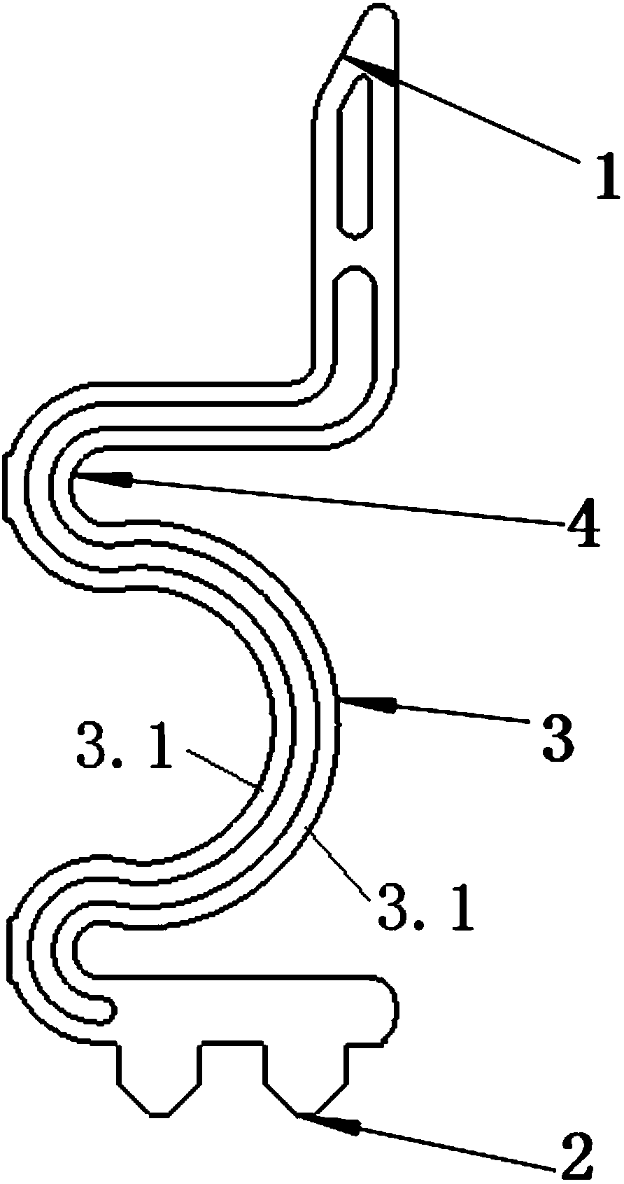
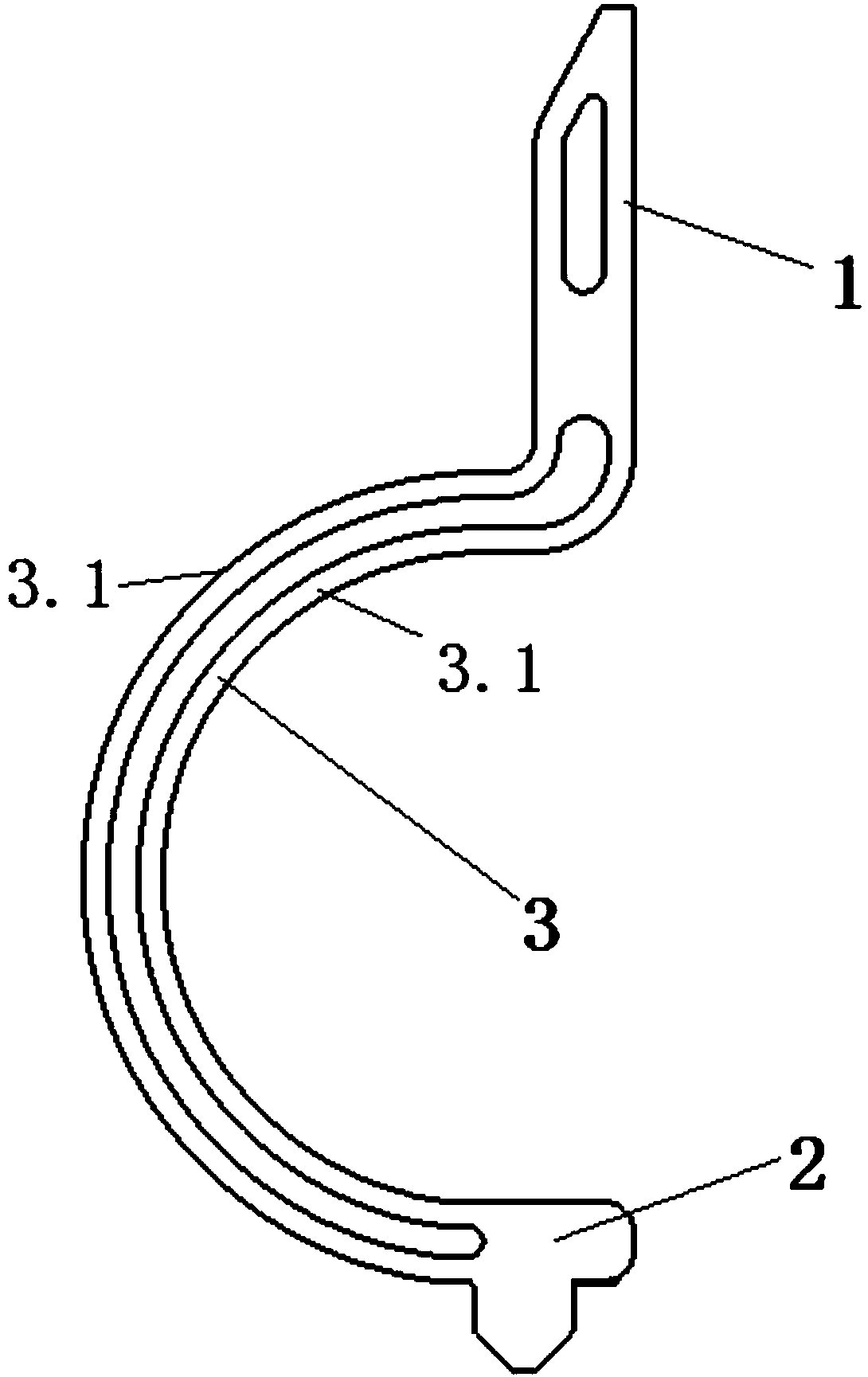
[0032] The crimping spring is a flat plate structure, which includes a first metal adapter part 1 for connecting the product connector, a second metal adapter part 2 for connecting the FPC, and a second metal adapter part 2 for connecting to the first metal adapter part 1 and the second metal adapter part. The metal bending part 3 between the metal switching parts 2, the first metal switching part 1, the second metal switching part 2 and the metal bending part 3 are integrally formed, and the first metal switching part 1 and the second metal switching part are integrally formed. The connecting part 2 is provided with a probe head, and the metal bending part 3 is composed of two metal conducting strips 3.1 arranged in parallel and spaced apart. The metal conduction strip 3.1 is C-shaped, the width of the probe head / 4≤the width of each metal conduction strip 3.1≤the width of the probe head / 3, the two ends of each metal conduction strip 3.1 are guided by se...

Example Embodiment

[0033] Implementation 2:

[0034] The crimping spring is a flat plate structure, which includes a first metal adapter part 1 for connecting the product connector, a second metal adapter part 2 for connecting the FPC, and a second metal adapter part 2 for connecting to the first metal adapter part 1 and the second metal adapter part. The metal bending part 3 between the metal switching parts 2, the first metal switching part 1, the second metal switching part 2 and the metal bending part 3 are integrally formed, and the first metal switching part 1 and the second metal switching part are integrally formed. The connecting part 2 is provided with a probe head, and the metal bending part 3 is composed of two metal conducting strips 3.1 arranged in parallel and spaced apart. The metal conduction strip 3.1 is C-shaped, and the width of the probe head / 4≤the width of each metal conduction strip 3.1≤the width of the probe head / 3. Compared with Embodiment 1, Embodiment 2 cannot achieve...

Example Embodiment

[0035] Implementation 3:

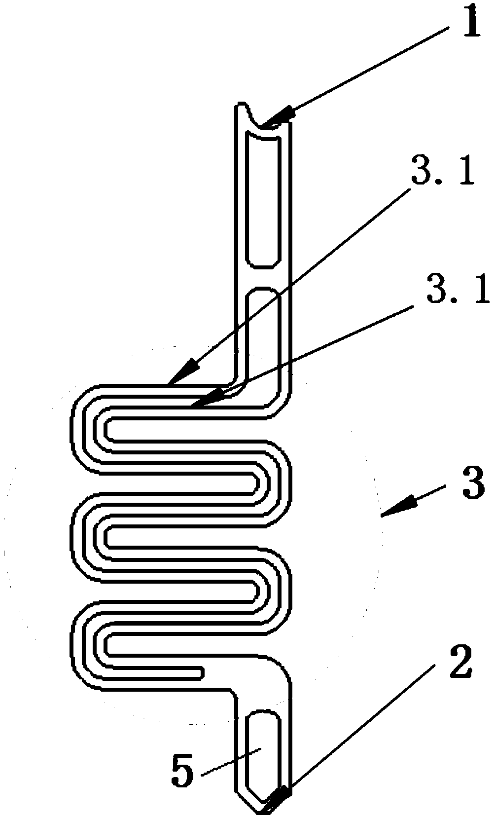
[0036] The crimping spring is a flat plate structure, which includes a first metal adapter part 1 for connecting the product connector, a second metal adapter part 2 for connecting the FPC, and a second metal adapter part 2 for connecting to the first metal adapter part 1 and the second metal adapter part. The metal bending part 3 between the metal switching parts 2, the first metal switching part 1, the second metal switching part 2 and the metal bending part 3 are integrally formed, and the first metal switching part 1 and the second metal switching part are integrally formed. The connecting part 2 is provided with a probe head, and the metal bending part 3 is composed of two metal conducting strips 3.1 arranged in parallel and spaced apart. The metal conduction strips 3.1 are multi-S-shaped, and the width of the probe head / 4≤the width of each metal conduction strip 3.1≤the width of the probe head / 3. The probe head on the second metal transition p...


PUM


Abstract

The invention discloses a crimping elastic piece of a single buffer channel. The crimping elastic sheet includes a first metal adapter portion, a second metal adapter portion and a metal bending portion; the first metal adapter portion, the second metal adapter portion and the metal bending portion are integrally formed; the first metal adapter portion and the second metal adapter portion have probe heads; the metal bending portion is composed of two metal conductive strips arranged in parallel and spaced from each other; each metal conductive strip is made of a material that is both electrically conductive and elastically deformable; the width of the probe heads/4 <= the width of each metal conductive strip <= the width of the probe heads/3. The invention is simple in structure and is convenient to use; the area of the metal bending portion for conduction is effectively increased by designing the width of the metal bending portion to be 2 to 4 times the width of the probe heads and designing the metal bending portion into the two parallel metal conductive strips spaced from each other; the impedance and continuity of the elastic sheet probe can be improved.

Description

technical field [0001] The invention relates to a crimping shrapnel, which belongs to the technical field of testing non-standard products such as electronic screens, and in particular to a crimping shrapnel with a single buffer channel. Background technique [0002] In the prior art, most of the conduction devices on the test fixture are pogo pin connectors. The pogo pin connector is formed by riveting the three basic components of the needle shaft, spring, and needle tube through precision instruments. Because the pogo pin The needle shaft of the connector is relatively thin and the aperture of the needle tube used to install the needle shaft is small, so the spring thimble connector has technical problems such as difficult processing and difficult control of processing accuracy. In order to solve the above technical problems, the Chinese utility model patent CN206515372U discloses a flat probe for integrated circuit testing, which includes an upper contact end, a bent sec...

Claims


Application Information

Patent Timeline
IPC IPC(8): G01R1/04G01R1/067
CPCG01R1/04G01R1/0416G01R1/06711G01R1/06716
Inventor 刘依玲浦佳王涛刘伯杨
Owner WUHAN JINGCE ELECTRONICS GRP CO LTD
Why Eureka
Try Eureka