Transapical implantable mitral valve device

A mitral valve, implantable technology, applied in the field of medical devices, can solve problems such as the internal collapse of the aortic outflow tract, and achieve the effect of ensuring the function

Active Publication Date: 2018-09-28
赛诺心畅医疗科技有限公司
View PDF6 Cites 10 Cited by
  • Summary
  • Abstract
  • Description
  • Claims
  • Application Information

AI Technical Summary

Problems solved by technology

[0007] The unique anatomy of the mitral valve poses significant challenges for transcatheter mitral valve replacement devices
Therefore, application of relatively large radial support forces on the mitral valve annulus, such as that imparted by expandable stents, may lead to collapse of the inner portion of the aortic outflow tract with potentially fatal consequences

Method used


Image

  • Transapical implantable mitral valve device
  • Transapical implantable mitral valve device
  • Transapical implantable mitral valve device

Examples


Embodiment 1

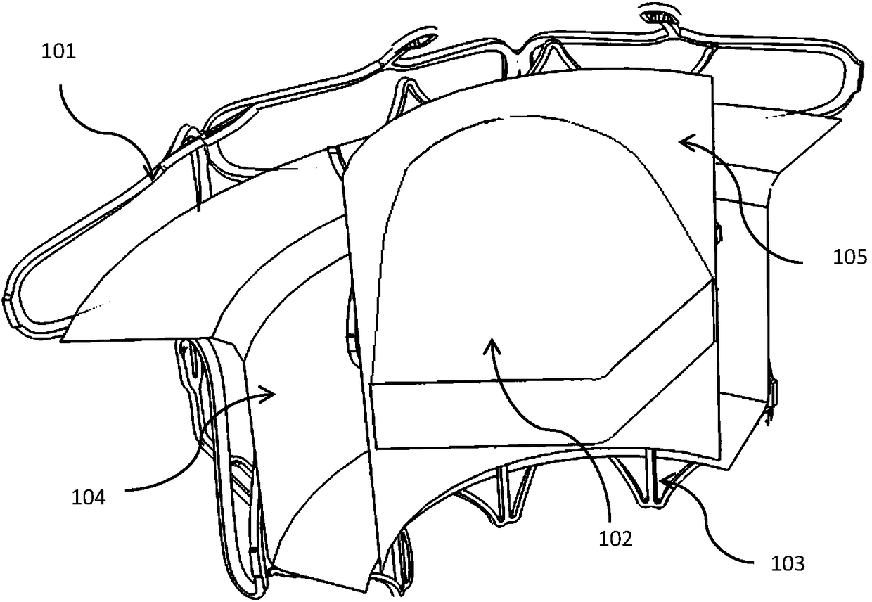
[0070] figure 1 It is a partial structural schematic diagram of a transapical implantable mitral valve device provided by the first embodiment of the present invention. Such as figure 1 As shown, in this embodiment, the transapical implantable mitral valve device includes: an outer valve stent 101, an inner valve stent 103, and a valve leaflet structure 102, as well as covering the inner surface of the outer valve stent 101 and / or Or the outer skirt 104 on the outer surface and the inner skirt 105 covering the inner surface and / or outer surface of the inner valve stent 103 .

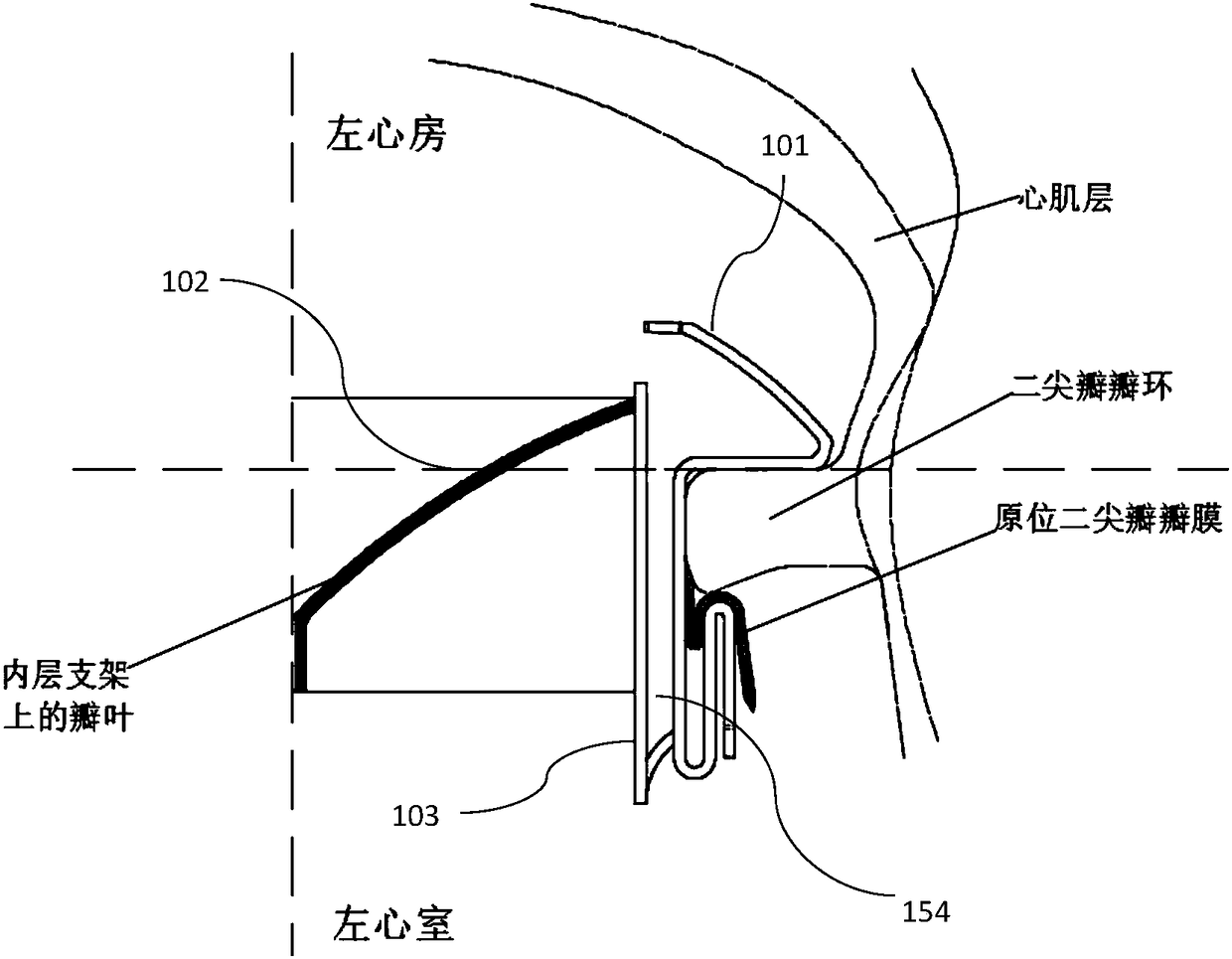
[0071] figure 2 It is a structural schematic diagram of a transapical implantable mitral valve device implanted in the human body provided by the first embodiment of the present invention. image 3 It is a schematic structural view of the outer valve stent in a transapical implantable mitral valve device provided by the first embodiment of the present invention. Such as Figure 1 to Figure 3 As sho...

Embodiment 2

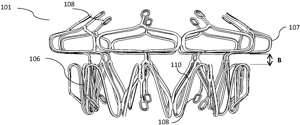
[0092] Figure 12 A schematic plan view of the outer valve stent in a transapical implantable mitral valve device provided in the second embodiment of the present invention; Figure 13 It is a schematic structural diagram of the outer valve stent in a transapical implantable mitral valve device provided by the second embodiment of the present invention. Such as Figure 12 and Figure 13 As shown, in this embodiment, the outer valve stent 201 provides radial support to the mitral valve annulus and can grab the mitral valve leaflets of human disease and fix them on the mitral valve annulus. Specifically, the outer valve stent 201 includes an annular network structure body composed of a plurality of first structural units 210 arranged in the circumferential direction, so as to provide radial support force for the mitral valve annulus, and include a support for the mitral valve device. The U-shaped structural unit 207 and the S-shaped structural unit 206 function as anchors. T...

Embodiment 3

[0101] In this embodiment, the inner valve stent in the transapically implantable mitral valve device is the same as that in Embodiment 1, and the outer valve stent is the same as in Embodiment 2. Figure 19 to Figure 21 It is a variety of rigid connection combinations that can be selected for the inner valve support and the outer valve support of the mitral valve device in the third embodiment of the present invention. Such as Figure 19 As shown, the inverted triangular second connecting structure 219 of the outer valve stent is stacked with the everted triangular first connecting structure 111 of the inner valve stent, and the third straight rod 251 of the outer valve stent is connected to the The first straight bars 114 of the inner valve stent intersect each other to form a rhombus shape, and the second vertex 223 of the inverted triangular second connecting structure 219 of the outer valve stent and the valgus triangle of the inner valve stent The first vertex 112 of th...


PUM


Abstract

The invention provides a transapical implantable mitral valve device. The transapical implantable mitral valve device comprises an outer valve stent, an inner valve stent and a valve leaflet structure. The outer valve stent comprises an outer valve stent body and an anchoring unit, the outer valve stent body is composed of a plurality of first structural units arranged in the circumferential direction, the anchoring unit is disposed on the outer valve stent body for anchoring the mitral valve device in the body, and the inner surface and / or the outer surface of the outer valve stent body is covered with an outer skirt. The inner valve stent is disposed in the outer valve stent and is connected with the outer valve stent, and a cavity is formed between the outer valve stent and the inner valve stent. The valve leaflet structure is disposed in the inner valve stent to form a prosthetic valve. The mitral valve device can ensure that a biological valve prosthesis is not affected by the irregular contour of the diseased mitral valve, an ideal contour is always maintained, and functions are ensured; and a platform for interventional therapy can be provided for a surgical-type mitral valve device.

Description

technical field [0001] The invention relates to the field of medical devices, in particular to a transapical implantable mitral valve device. Background technique [0002] Mitral regurgitation (MR) refers to that the mitral valve does not close tightly during systole, allowing blood to flow backward from the left ventricle into the left atrium. There are many reasons for valvular regurgitation, such as valvular prolapse, valvular sclerosis in the elderly, rheumatic valvular disease in teenagers and young and middle-aged people, infectious inflammation of valves, enlarged heart, etc. This prevents the left ventricle from filling during diastole. [0003] The presentation of mitral regurgitation varies widely in terms of severity. Mild mitral regurgitation can be asymptomatic for a long time and has a good prognosis; severe mitral regurgitation can lead to pulmonary hypertension, atrial fibrillation (AF), heart failure (HF), shock, and death . According to the severity of ...

Claims


Application Information

Patent Timeline
Patent Type & Authority Applications(China)
IPC IPC(8): A61F2/24
CPCA61F2/2412A61F2/2418A61F2/2466A61F2210/0014A61F2220/005A61F2220/0075A61F2230/005A61F2220/0008A61F2250/006A61F2230/0013A61L27/16A61L27/3625
Inventor 李中华李天竹马剑翔赵金红孟磊
Owner 赛诺心畅医疗科技有限公司
Why Eureka
Try Eureka