Device for separating oil-containing silt by liquid-state CO2

A CO2, liquid technology, applied in the direction of sludge treatment, water/sludge/sewage treatment, mining wastewater treatment, etc., can solve the problems of incomplete removal, secondary pollution, high cost, etc., to achieve mature liquefaction technology, complete separation, low cost effect

Active Publication Date: 2018-09-28
东营金岛环境工程有限公司 +1
View PDF5 Cites 1 Cited by
  • Summary
  • Abstract
  • Description
  • Claims
  • Application Information

AI Technical Summary

Problems solved by technology

However, there are various problems of high cost, low efficiency, long cycle, and incomplete removal, especia

Method used


Image

  • Device for separating oil-containing silt by liquid-state CO2

Examples


Embodiment Construction

[0015] In conjunction with the accompanying drawings, the present invention is described in further detail below:

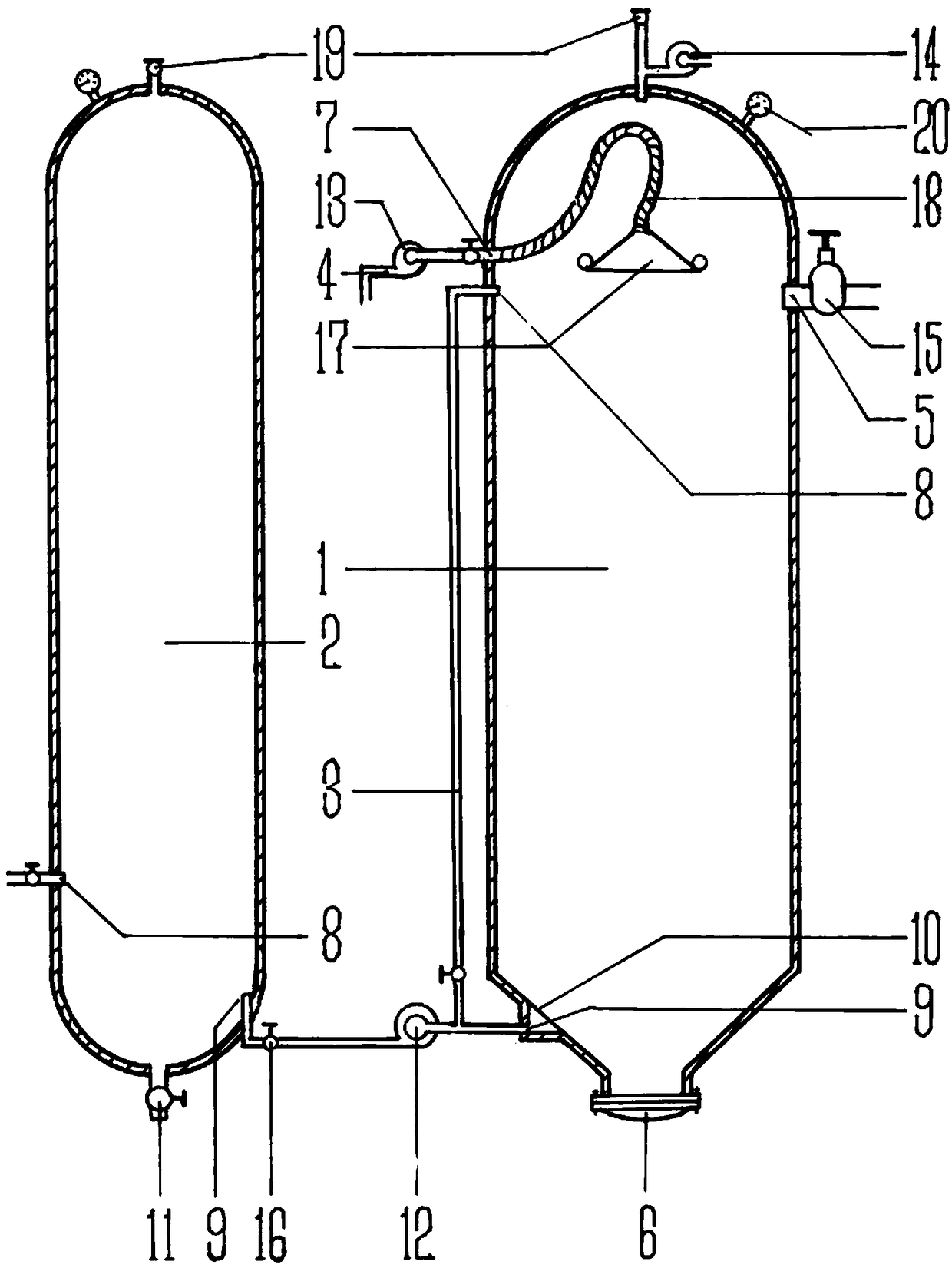
[0016] Such as figure 1 Shown, liquid CO 2 The oily sediment separation device is mainly composed of separation tower 1 and liquid CO 2 The storage tank 2 is composed of two parts, both of which are steel cylindrical sealed structures capable of withstanding a pressure of 15 MPa. An oily sediment inlet 5 controlled by a cut-off valve 15 is arranged on the side wall of the upper part of the separation tower 1. The bottom umbrella shape is narrowed, and the central position is designed as a sediment outlet 6 closed by a flange cover plate. The middle part of the hypotenuse is designed by a The CO separated by the filter membrane 10 and protruding outward 2 import and export9. Set oil-water outlet 7 and CO on the opposite side wall of oily sediment inlet 5 2 Entrance 8. The oil-water outlet 7 is connected inwardly to the umbrella-shaped oil collecting cover 17...


PUM


Abstract

The invention discloses a device for separating oil-containing silt by liquid-state CO2. The device is characterized in that the physical properties of ultralow viscosity, ultrahigh flowability and seepage performance, high density and ultrahigh adsorption power of the liquid-state CO2 are used; the separation and collection of the oil-containing silt is completed in a supercritical pressure separation tower; the goals of environment protection and resource utilization are achieved. Compared with the prior art, the device has the advantages that the cost is low; the efficiency is high; the separation is thorough; the raw material sources are wide and rich. The device has the characteristics that no new harmful substance is generated in the whole processing process; the new pollution and the thus required secondary government are avoided. The special beneficial effects and action are realized on the duplex significance of environment protection and resource utilization, so that good popularization and application values are realized.

Description

1. Technical field [0001] The invention relates to the treatment of oily sediment on the surface of an oil field, in particular to a liquid CO 2 Separation of oily sediment device. 2. Background technology [0002] In the process of drilling, exploration, oil production, transportation, workover, etc. in the oil field, in the refining and use of oil, and accidents in the above process, some crude oil will always fall to the ground, polluting the land in the oil area, deteriorating the oil area ecological environment. How to control this part of oily sediment has always been a major problem faced by the petroleum and petrochemical industries. From the chemical point of view, the existing technology adopts incineration and chemical cleaning. Degradation methods, etc., and combined application of various methods. However, there are various problems such as high cost, low efficiency, long cycle, and incomplete removal. In particular, there are secondary pollution and retreatm...

Claims


Application Information

Patent Timeline
IPC IPC(8): C02F11/00C02F103/10
CPCC02F11/00C02F2103/10
Inventor 于国明刘东张俊锋梁玉海刘德华
Owner 东营金岛环境工程有限公司
Why Eureka
Try Eureka