Method for reducing loss of hot bending glass die and equipment thereof

A glass mold and mold technology, applied in glass manufacturing equipment, glass molding, glass re-molding and other directions, can solve the problems of destroying the structure of graphite molds, expensive graphite molds, affecting the cost of curved glass, etc. The effect of longevity and easy operation

Inactive Publication Date: 2018-09-28
惠州纽卡沃科技有限公司
View PDF4 Cites 5 Cited by
  • Summary
  • Abstract
  • Description
  • Claims
  • Application Information

AI Technical Summary

Problems solved by technology

During the heating process, the glass cover forms a similar airtight space above the air, so the oxygen in the air is not easy to escape, and as the temperature rises, it will react in the cavity, and the loss of the mold cavity will be lost. Carbon, which in turn destroys the structure of the graphite mold, resulting in processing deviations in the subsequent glass forming process
[0004] Faced with this situation, the graphite mold can only be replaced frequently to ensure the accuracy of the finished product, but the graphite mold itself is expensive, and the price is even worse after processing, so this aspect has long affected the cost of curved glass

Method used


Image

  • Method for reducing loss of hot bending glass die and equipment thereof
  • Method for reducing loss of hot bending glass die and equipment thereof
  • Method for reducing loss of hot bending glass die and equipment thereof

Examples


Embodiment 1

[0048] In this embodiment, nitrogen is used as the protective gas, high-pressure gas flushing is used for the first replacement of external air, and the second replacement of air inside the mold 1 is carried out by sending it into the equipment for vacuuming and then using nitrogen.

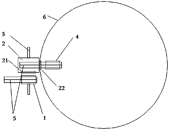
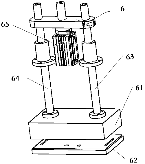
[0049] as attached figure 2 As shown, the mold 1 passes through the bottom bracket 62 on the track 5 for transportation, and when it is transmitted laterally, it is pushed laterally by the push cylinder 3 .

[0050] The sealed space 2 adopts a sealed glass cover, and a first automatic door 21 is arranged on one side of the sealed glass cover, which can be opened or closed according to program control. The sealed glass cover and the equipment are airtightly connected, and a The second automatic door 22 can also be controlled to open or close according to the program.

[0051] The processing equipment 4 is a high-temperature heating equipment, and the interior of the processing equipment 4 is a p...

Embodiment 2

[0059] In this embodiment, the difference from Embodiment 1 is that the vacuum extraction equipment is not installed in the processing equipment 4, but is installed in the enclosed space 2, and in addition, the enclosed space 2 is also provided with another machine to extract the enclosed space 2. Vacuum equipment.

[0060] After the mold 1 to be processed is sent into the closed space 2, the second automatic door 22 is not opened, but the vacuuming equipment of the closed space 2 is started to vacuumize the whole closed space 2 and inject nitrogen gas. Then vacuumize the inside of the mold 1 and inject nitrogen gas. After vacuuming twice, the second automatic door 22 is opened again, and the mold 1 is sent into the processing equipment 4 . The embodiments of the present invention have been described in detail above in conjunction with the accompanying drawings, but the present invention is not limited to the above-mentioned embodiments. kind of change.


PUM


Abstract

The invention discloses a method for reducing loss of a hot bending glass die and equipment thereof. The method comprises the following steps: S10) placing glass in a bottom die, and placing an upperdie at an upper part of glass; S20) placing the die in an enclosed space, and displacing air outside the die to protection gas which cannot perform a chemical reaction with the die under high temperature condition; S30) displacing residual air in the die to the protection gas; and S40) pushing the die to a processing station in the processing equipment. Through two-time gas replacing on the die, the gas outside the die and the gas in the die can be respectively replaced to the protection gas, so that corrosion of the die can be prevented during processing, the service life is increased, by dividing two-time displacing, work can be carried out with pertinency, air processing effect is increased, and the cost is reduced.

Description

technical field [0001] The invention relates to the field of hot bending of glass, in particular to the protection of a hot bending mold during the glass hot bending process. Background technique [0002] At present, in the process of producing curved glass for mobile phones, the flat glass is usually placed in a prefabricated graphite mold. After the graphite mold is heated as a whole, the glass reaches the critical melting point and will be deformed according to the prefabricated shape to achieve the predetermined The effect of the curved shape. [0003] However, it is found in actual processing that at high temperature, the graphite mold will react with the oxygen in the air, which will cause damage to the collision in the inner molding cavity of the mold. as attached figure 1 As shown, especially in the feeding process, the glass itself is a plane structure, and the plane is a curved structure in the molding cavity. There is a certain gap between the two, and there is ...

Claims


Application Information

Patent Timeline
Patent Type & Authority Applications(China)
IPC IPC(8): C03B23/03
CPCC03B23/0302
Inventor 李国勇
Owner 惠州纽卡沃科技有限公司
Why Eureka
Try Eureka