Plate peeling machine group

A stripping and unit technology, applied in the direction of electrolysis components, electrolysis process, etc., can solve the problems of clip edge rubbing, collision, cathode plate stripping knife scratches, conductive rod lifting, etc., to ensure surface quality and avoid peeling difficulties. , the effect of preventing corner space

Pending Publication Date: 2018-09-28
株洲优瑞科有色装备有限公司
View PDF0 Cites 7 Cited by
  • Summary
  • Abstract
  • Description
  • Claims
  • Application Information

AI Technical Summary

Problems solved by technology

[0002] The stripping unit is used to strip the deposition plates (such as cathode copper, cathode zinc, etc.) deposited on the cathode plate in the permanent stainless steel cathode electrolysis process. The deposition plates are deposited on the front and rear sides of the cathode plate. When the unit is performing the stripping operation of the deposition plate from the cathode plate, the stripping knife often enters between the deposition plate and the cathode plate through the rotation of the parallel plate body. In this process, the cathode plate needs to be deformed by the flexure device to make the cathode copper and the cathode plate The plate separates the opening at the position of the liquid level line, which makes the curved cathode plate easily scratched by the stripping knife, resulting in increased adhesion between the deposition plate and the cathode plate, greatly increasing the final peeling of the deposition plate from the cathode plate difficulty
[0003] In addition, in order to prevent the two sides of the two deposition plates before and after the cathode plate from sticking together, both sides of the cathode plate are usually covered with insulating edge strips (ie, edge strips), and the edge strips usually need to protrude from the bottom of the cathode plate for a certain distance ( That is, it is exposed at the bottom of the cathode plate, generally 3 to 5 mm) to ensure that the two corners of the bottom of the cathode plate do not grow electrolytic metal. Scratches and collisions often occur on the side strips, causing the part of the side strip exposed at the bottom to go up. During the electrolysis process, the two corners at the bottom of the cathode plate are easily wrapped by electrolytic metal, which affects the peeling of the final deposition plate.
[0004] In addition, the bottom of the conductive rod on the cathode plate needs to be cleaned after each electrolysis to ensure its excellent conductivity and improve the efficiency of electrolysis. The existing stripping unit generally does not have an active cleaning device, usually There is a fixed brush at the electrical contact position of the conductive rod of the plate chain frame. When the cathode plate passes the brush during the chain movement, the electrical contact point is cleaned. Although some stripping units are equipped with active cleaning devices, However, these cleaning devices only have the function of rotating and scrubbing the conductive rods. However, the brush head of the active cleaning device may be worn after a long time of brushing work. To have a good scrubbing effect, the brush head not only needs to contact the conductive rod, but also needs to press the conductive rod. Of course, the brush head cannot lift the conductive rod when pressing the conductive rod. Obviously, the active cleaning device of the prior art cannot do this. until thoroughly scrubbing the conductive rod
[0005] In addition, the stripping unit of the prior art generally sets the distance between the pole plates that are about to enter the washing chamber to a constant value (such as 100mm), and the distance between the pole plates is small (the pole plate refers to the entire cathode plate with the deposition plate attached to the surface) , after entering the washing room, most of the plate body only relies on water to flow on its surface to take away the electrolyte and anode slime, and the upper spray water and the side spray water overlap each other due to the large overlap of spray areas. Obviously, the washing effect is poor

Method used


Image

  • Plate peeling machine group
  • Plate peeling machine group
  • Plate peeling machine group

Examples


Embodiment 1

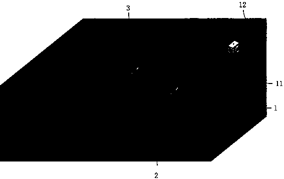
[0049] Such as figure 1 The stripping unit shown includes a plate input system 1, a stripping system 2 and a conductive rod cleaning system 3. The plate input system 1 is used to transport the electrolyzed cathode plate B to the stripping system 2, and the stripping system System 2 is used for stripping the deposition plate, and the conductive rod cleaning system 3 is used for brushing the conductive rod of the cathode plate after the deposition plate is peeled off to prepare for the next electrolysis cycle.

[0050] The plate input system 1 includes a washing room 11 for cleaning the plates, and a push plate distance expanding device 12 that can expand the distance between the plates to be transported into the washing room.

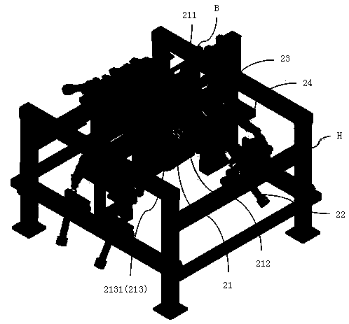
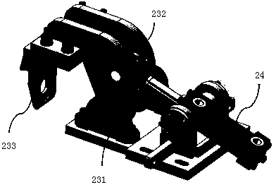
[0051] The stripping system 2 includes a swing arm stripping device that enters from the top of the deposition plate to separate the deposition plate from the cathode plate B, and also includes an auxiliary separation device that enters from both sides o...


PUM


Abstract

The invention belongs to the technical field of electrolysis smelting, and discloses a plate peeling machine group. The machine group comprises a plate peeling system used for peeling sedimentation plates off, an electrode plate inputting system used for delivering electrolyzed cathode plates to the plate peeling system, and a conductive bar cleaning and brushing system used for cleaning and brushing the peeled cathode plates so that the cathode plates can enter the next electrolysis circulation; the electrode plate inputting system comprises a washing chamber and a push plate range expandingdevice used for expanding the range between the electrode plates to be put into the washing chamber; the plate peeling system comprises a swing arm type plate peeling device entering from the part above the sedimentation plates to peel the sedimentation plates off from the cathode plates and an auxiliary separation device entering from the two sides of the sedimentation plates to assist separation; the conductive bar cleaning and brushing system comprises a conductive bar cleaning and brushing device used for cleaning conductive bars of the cathode plates. According to the machine group, by the arrangement of the plate peeling system, the scratching of the surfaces of the cathode plates can be prevented to reduce the peeling difficulty of the sedimentation plates, by the arrangement of theconductive bar cleaning and brushing system, the conductive bars can be timely cleaned to reduce the resistance of the cathode plates and improve the electrolysis efficiency of a workshop, by the arrangement of the electrode plate inputting system, the electrode plates can be thoroughly cleaned, and finally the sedimentation plates with high quality can be obtained.

Description

technical field [0001] The invention relates to the technical field of electrolytic smelting, in particular to a stripping unit. Background technique [0002] The stripping unit is used to strip the deposition plates (such as cathode copper, cathode zinc, etc.) deposited on the cathode plate in the permanent stainless steel cathode electrolysis process. The deposition plates are deposited on the front and rear sides of the cathode plate. When the unit is performing the stripping operation of the deposition plate from the cathode plate, the stripping knife often enters between the deposition plate and the cathode plate through the rotation of the parallel plate body. In this process, the cathode plate needs to be deformed by the flexure device to make the cathode copper and the cathode plate The plate separates the opening at the position of the liquid level line, which makes the curved cathode plate easily scratched by the stripping knife, resulting in increased adhesion bet...

Claims


Application Information

Patent Timeline
Patent Type & Authority Applications(China)
IPC IPC(8): C25C7/08
CPCC25C7/08
Inventor 刘望保刘秉王皓炜王勇刚马超胡少龙邓瑛李广志
Owner 株洲优瑞科有色装备有限公司
Why Eureka
Try Eureka