Core tube shaft structure of super high-rise building

A core tube and shaft structure technology, which is applied in building components, special structures, building structures, etc., can solve the problems of horizontal ribs affecting the climbing of the top form, complicated construction process, unfavorable progress and quality of core tube construction, etc.

Active Publication Date: 2018-09-28
浙江绿创新拓建筑规划设计有限公司
View PDF7 Cites 2 Cited by
  • Summary
  • Abstract
  • Description
  • Claims
  • Application Information

AI Technical Summary

Problems solved by technology

Although using this method to reserve the reinforcement of the core tube effectively solves the problem that the horizontal reinforcement affects the climb of the top form, this method needs to cut out the reserved reinforcement and perform subsequent processing to ensure that the reinforcement and Concrete Grip
Obviously, the construction process is more complicated
Considering the workload and construction difficulty of reinforcement treatment in the later stage, the above existing methods are not conducive to the progress and quality of core tube pouring construction

Method used


Image

  • Core tube shaft structure of super high-rise building
  • Core tube shaft structure of super high-rise building
  • Core tube shaft structure of super high-rise building

Examples


Embodiment Construction

[0024] The present invention will be further described below in conjunction with the accompanying drawings.

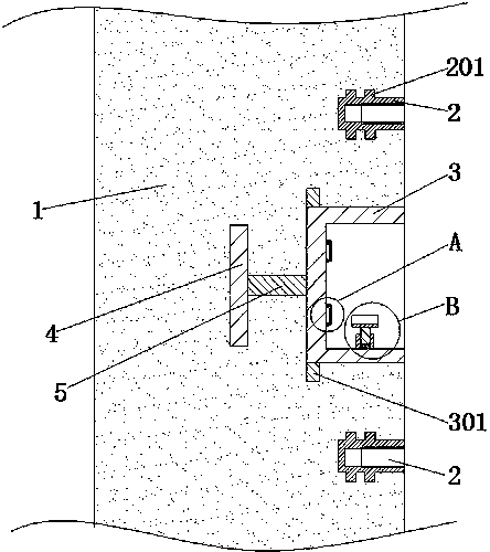
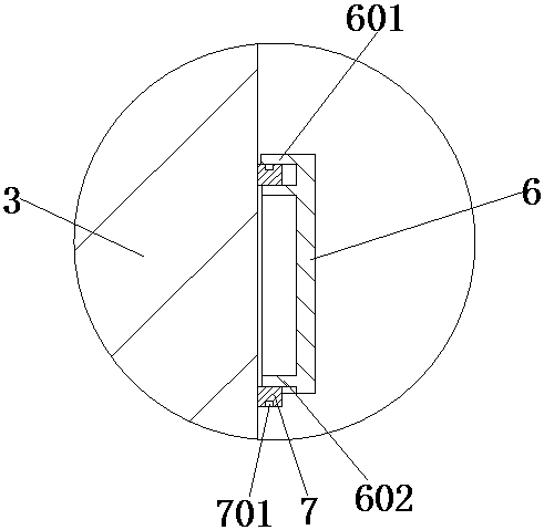
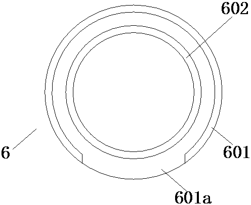
[0025] Such as Figures 1 to 5 Shown, a kind of super high-rise building core tube axle structure described in the present invention, it comprises wall body 1 and support member; The inside of described wall body 1 is pre-embedded with channel steel 3; The axial direction of described channel steel 3 The direction and the horizontal plane are arranged parallel to each other; the opening end face of the channel steel 3 and the side surface of the wall 1 are arranged in the same vertical plane; the bottom of the channel steel 3 is fixed with several connecting rods 5; The end of the rod 5 is fixed with a circular plate 4; the connecting rod 5 and the circular plate 4 are pre-embedded behind the wall 1, so that the channel steel 3 is fixed in the wall 1 as a whole, and the channel steel 3 will not face the wall in this structure. The body forming sliding form slides on t...


PUM


Abstract

The invention relates to the technical field of core tube shaft structures, in particular to a core tube shaft structure of a super high-rise building. Channel steel is pre-embedded in a wall body, and a plurality of welding positioning devices are arranged in the channel steel. The welding positioning devices each comprise fixing ring groups and positioning columns, and one end surfaces of fixingrings are fixed to the inner bottom wall of the channel steel. Internal thread sleeves are fixed to the upper and lower sides of the channel steel in a pre-embedded mode, and the fixing rings are tightly embedded between outer rings and inner rings. The end faces of the outer rings are pressed against the inner bottom wall of the channel steel, and water stop concave rings are arranged on the outer side walls of the fixing rings. The opening direction of each open groove faces the ground. When the core tube shaft structure is used, the structure improves the waterproof ability of the fixing rings and ensures the welding quality of bacillus and the fixing rings; through the support between the fixing rings and supporting members, the welding difficulty of upper reinforcement which is not shown in a floor slab drawing is reduced; and after the reinforcement is welded, a supporting point of construction is provided for a template through the internal thread sleeves, and the difficulty ofthe template construction is reduced.

Description

technical field [0001] The invention relates to the technical field of core cylinder shaft structures, in particular to a core cylinder shaft structure for super high-rise buildings. Background technique [0002] At present, super high-rise core tube construction generally adopts top formwork for construction. During construction, generally the vertical structure of the core tube is constructed first, followed by the horizontal structure. In order not to affect the top formwork construction of the vertical structure of the core tube, the ribs reserved for the horizontal structure are bent into the core tube wall and poured at the same time as the wall concrete, and the reserved ribs are removed during the later horizontal structure construction . Although using this method to reserve the reinforcement of the core tube effectively solves the problem that the horizontal reinforcement affects the climb of the top form, this method needs to cut out the reserved reinforcement...

Claims


Application Information

Patent Timeline
Patent Type & Authority Applications(China)
IPC IPC(8): E04B1/34E04B2/00E04B1/66
CPCE04B1/34E04B1/66E04B2/00
Inventor 林再颐
Owner 浙江绿创新拓建筑规划设计有限公司
Why Eureka
Try Eureka