Crank-connecting rod mechanism capable of achieving Miller cycle and control method

A technology of crank-link mechanism and Miller cycle, which is applied in the direction of crank, connecting rod bearing, crankshaft, etc., can solve the problems of difficult response speed of stepping motor, difficult dynamic compression ratio control, and reduced control reliability, etc., to achieve reduction The effect of small development workload, small driving torque, and large control flexibility

Active Publication Date: 2018-09-28
XIHUA UNIV
View PDF17 Cites 5 Cited by
  • Summary
  • Abstract
  • Description
  • Claims
  • Application Information

AI Technical Summary

Problems solved by technology

Although the above solutions can change the compression ratio, changing the position of the crankshaft involves redesigning the devices related to the position of the crankshaft, such as the flywheel at the output end, which makes the structure of the engine very complicated; changing the shape of the piston will cause its dynamic compression more difficult than control
Changing the relative position of the connecting rod and the crankshaft is highly feasible, such as the technical solution proposed in pat

Method used


Image

  • Crank-connecting rod mechanism capable of achieving Miller cycle and control method
  • Crank-connecting rod mechanism capable of achieving Miller cycle and control method
  • Crank-connecting rod mechanism capable of achieving Miller cycle and control method

Examples


Embodiment Construction

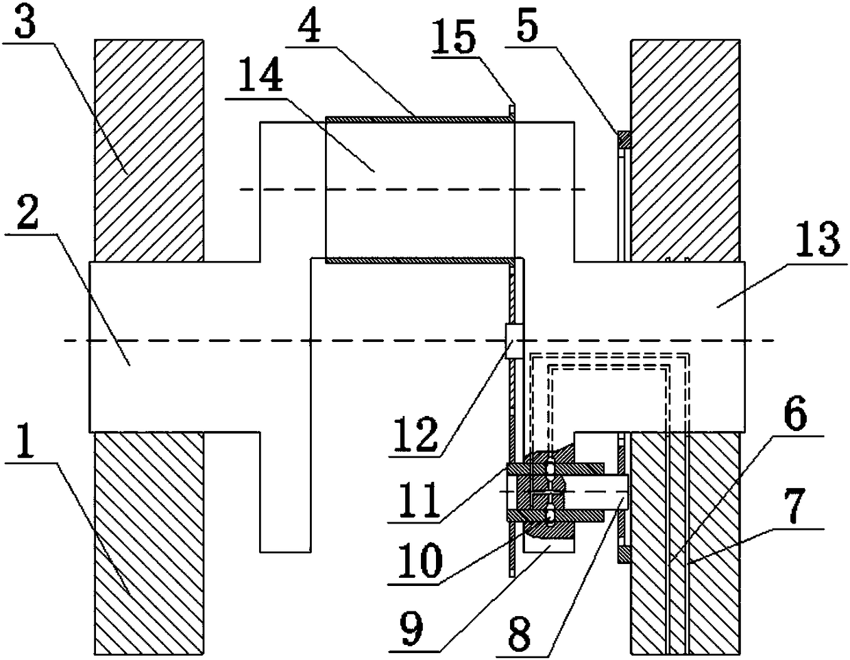
[0044] The present invention will be described in further detail below in conjunction with the accompanying drawings and specific embodiments. Such as figure 1 As shown, a crank-link mechanism capable of realizing the Miller cycle includes a crankshaft 2 , a crankshaft support cover 1 , a crankshaft support seat 3 , a drive gear assembly 11 , a planetary gear assembly 8 and a lock pin 10 .

[0045] Described crankshaft support seat 3 is a part of engine body, is mainly used for installing crankshaft 2, and crankshaft support cover 1 is paired with described crankshaft support seat 3 to form cylindrical hole, and all cylindrical holes in an engine keep coaxial.

[0046] The crankshaft 2 includes a main journal 13 , a pin journal 3 and a crankshaft balance weight 9 which are fixedly connected to each other.

[0047] The main journal 13 is rotatably installed in the cylindrical hole formed by the crankshaft support cover 1 and the crankshaft support seat 3; the inner wall of the...


PUM


Abstract

The invention discloses a crank-connecting rod mechanism capable of achieving the Miller cycle and a control method. A driving oil channel and a locking oil channel are arranged in a crankshaft, an eccentric connecting rod bearing is arranged on a connecting rod neck of the crankshaft, a driving gear which meshes with an outer meshing gear ring of the eccentric connecting rod bearing through an idle gear is installed in a crankshaft balancing block, a planetary gear is installed in a driving gear hollow shaft, and the driving gear hollow shaft is provided with locking pins capable of locking the hollow shaft and the crankshaft balancing block or locking the hollow shaft and a planetary gear shaft; and the driving gear hollow shaft and the planetary gear shaft are locked by applying hydraulic oil to the driving oil channel to enable the planetary gear shaft to transmit movement to the driving gear and then transmit movement to the outer meshing gear ring of the eccentric connecting rodbearing through the idle gear, the eccentric connecting rod bearing rotates around the connecting rod neck of the crankshaft, and then the compression ratio of an engine is changed. According to the crank-connecting rod mechanism capable of achieving the Miller cycle and the control method, the crank-connecting rod mechanism can achieve synchronous movement with rotation of the engine, compressionratio adjustment of the engine in one working stroke can be achieved, then the Miller cycle is achieved, the control flexibility is high, and control is flexible.

Description

technical field [0001] The invention relates to the technical field of piston internal combustion engines, in particular to a crank connecting rod mechanism capable of realizing the Miller cycle and a control method. Background technique [0002] Piston internal combustion engines are widely used as power sources in vehicles, non-road mobile machinery, ships and some stationary generator sets, making important contributions to the development of the national economy. With the development of economy and industrial technology, the number of piston internal combustion engines continues to increase, which has brought great pressure to energy and the environment. Therefore, energy saving and emission reduction have always been the pursuit goals of piston internal combustion engine workers. [0003] Typically, when the compression ratio of a piston internal combustion engine is increased, its fuel economy and emissions levels can be improved. However, when the load of the engine...

Claims


Application Information

Patent Timeline
IPC IPC(8): F02B75/04
CPCF02B75/04Y02T10/12F16C9/04F16C9/02F16C3/14F02B75/048F16F15/283F16H57/0479F16C3/28F16H1/28
Inventor 田维楚云路胡明艳肖邦吴学舜韩志强
Owner XIHUA UNIV
Why Eureka
Try Eureka