Hazardous waste efficient incineration device

An incineration device and hazardous waste technology, applied in the field of high-efficiency hazardous waste incineration devices, can solve the problems of high cost, high cost of hazardous waste disposal, environmental pollution, etc.

Inactive Publication Date: 2018-09-28
石力峰
View PDF5 Cites 5 Cited by
  • Summary
  • Abstract
  • Description
  • Claims
  • Application Information

AI Technical Summary

Problems solved by technology

[0002] With the development of industry, the hazardous waste discharged in the industrial production process is increasing day by day. Due to the serious pollution and potential serious impact of hazardous waste, hazardous waste has been called "political waste" in industrially developed countries, and the public is very concerned about the problem of hazardous waste. Sensitive, opposed to setting up hazardous waste disposal sites in the areas where they live, and the high cost of hazardous waste disposal, so it is particularly difficult to efficiently treat hazardous waste. In the process of processing hazardous waste, heat treatment is one of the most effective means. Heat treatment is to destroy and change the composition and structure of solid waste through high temperature, and at the same time achieve the purpose of volume reduction, harmlessness or comprehensive utilization. The methods include incineration, pyrolysis, wet oxidation, roasting, sintering, etc. Large wastes are harmlessly treated by incineration treatment process, and the waste heat of incineration is recovered for comprehensive utilization, which can reduce the treatment cost and energy waste, but the existing device structure is relatively complicated, the cost is high, and it is difficult to use it on a large scale. Lack of tail gas treatment, harmful gases are directly discharged into the air, causing great environmental pollution

Method used


Image

  • Hazardous waste efficient incineration device
  • Hazardous waste efficient incineration device
  • Hazardous waste efficient incineration device

Examples


Embodiment Construction

[0013] The following will clearly and completely describe the technical solutions in the embodiments of the present invention with reference to the accompanying drawings in the embodiments of the present invention. Obviously, the described embodiments are only some, not all, embodiments of the present invention. Based on the embodiments of the present invention, all other embodiments obtained by persons of ordinary skill in the art without making creative efforts belong to the protection scope of the present invention.

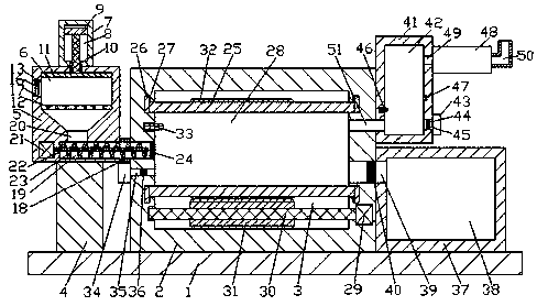
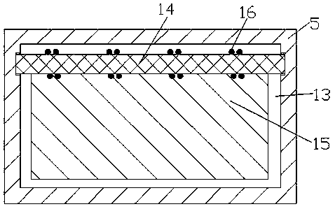
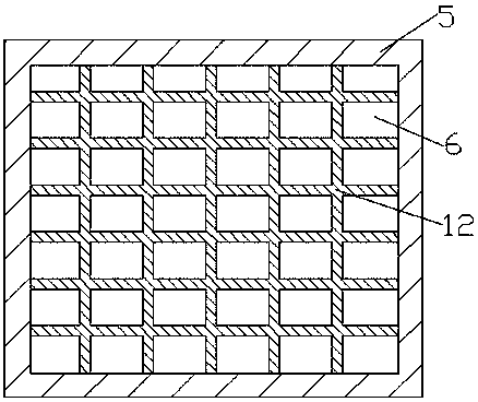
[0014] see Figure 1-4, an embodiment provided by the present invention: a hazardous waste high-efficiency incineration device, including a fixed bottom plate 1, a fixed shell 2 is fixedly arranged at the middle position of the upper end surface of the fixed bottom plate 1, and the inside of the fixed shell 2 is set There is a sealed space 3, a support platform 4 is arranged on the left side of the upper end surface of the fixed bottom plate 1, a pretreatment ...


PUM


Abstract

The invention discloses a hazardous waste efficient incineration device which comprises a fixed base plate. A fixed shell is fixedly arranged at the middle position of the upper end face of the fixedbase plate, a sealed space is arranged inside the fixed shell, a supporting table is arranged on the left side of the upper end face of the fixed base plate, a pre-treating box is fixedly connected tothe upper end face of the supporting table, a hydraulic shell integrated with the pre-treating box is arranged at the middle portion of the upper end face of the pre-treating box, an incineration pipe is arranged inside the sealed space, a collecting box is fixedly arranged at the position, on the right side of the fixed shell, on the upper end face of the fixed base plate, a burning box extending upwards is fixedly arranged on the upper side of the right end face of the fixed shell, and a heat recovering device is fixedly arranged at the upper end of the right end face of the burning box. When the device works, the heat recovering device can absorb heat of gas discharged from the burning space, the quick cooling effect is achieved, and regeneration of harmful gas is prevented; and meanwhile, the heat energy is absorbed through the heat recovering device, and energy saving is saved.

Description

technical field [0001] The invention relates to the field of garbage incineration, in particular to a high-efficiency hazardous waste incineration device. Background technique [0002] With the development of industry, the hazardous waste discharged in the industrial production process is increasing day by day. Due to the serious pollution and potential serious impact of hazardous waste, hazardous waste has been called "political waste" in industrially developed countries, and the public is very concerned about the problem of hazardous waste. Sensitive, opposed to setting up hazardous waste disposal sites in the areas where they live, and the high cost of hazardous waste disposal, so it is particularly difficult to efficiently treat hazardous waste. In the process of processing hazardous waste, heat treatment is one of the most effective means. Heat treatment is to destroy and change the composition and structure of solid waste through high temperature, and at the same time ...

Claims


Application Information

Patent Timeline
Patent Type & Authority Applications(China)
IPC IPC(8): F23G5/033F23G5/32F23G5/44F23G5/46
CPCF23G5/033F23G5/32F23G5/444F23G5/46F23G2201/80F23G2206/20
Inventor 石力峰
Owner 石力峰
Why Eureka
Try Eureka