Corrugated tray bridge adopting toothed multi-pole T-type joint projection welding

A multi-pole, corrugated technology, applied in the direction of electrical components, etc., can solve the problems that hinder the production and technological progress of high-strength topology thin-plate cable trays, and achieve the effects of no deformation, reduced production costs, and high precision

Pending Publication Date: 2018-09-28
JIANGSU ONEQ ELECTRICAL APPLIANCE GRP
View PDF0 Cites 10 Cited by
  • Summary
  • Abstract
  • Description
  • Claims
  • Application Information

AI Technical Summary

Problems solved by technology

In addition, with this welding method, thin plates less than 0.7mm cannot be welded, which seriously hinders the production and technological progress of high-strength topological structure thin plate cable trays

Method used


Image

  • Corrugated tray bridge adopting toothed multi-pole T-type joint projection welding
  • Corrugated tray bridge adopting toothed multi-pole T-type joint projection welding
  • Corrugated tray bridge adopting toothed multi-pole T-type joint projection welding

Examples


Embodiment Construction

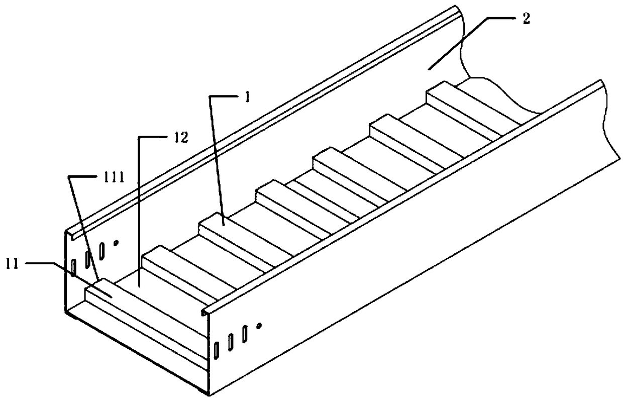
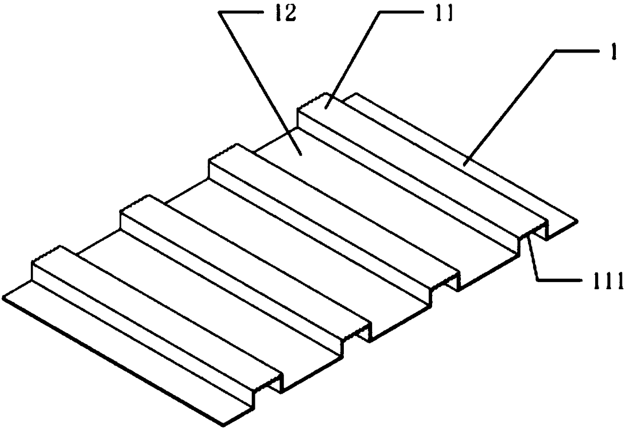
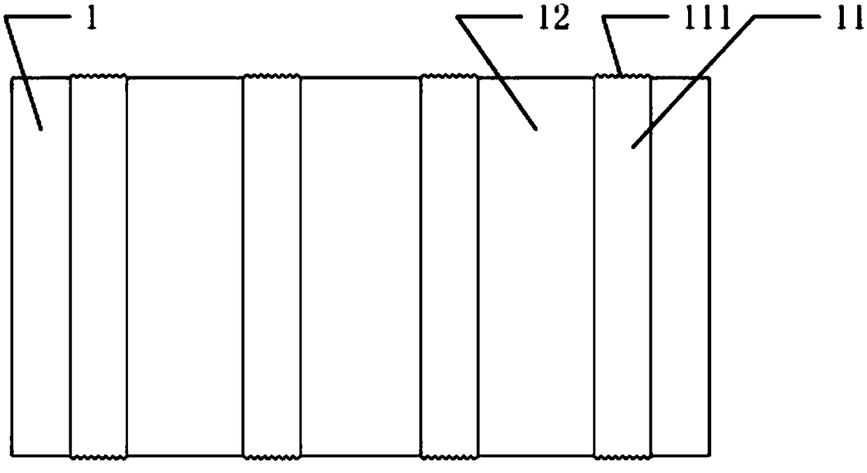
[0020] A corrugated pallet bridge adopting tooth-shaped multi-pole T-shaped connection projection welding of the present invention includes a bottom plate 1, bottom plate protrusions 11, bottom plate protrusion end face tooth shapes 111, bottom plate grooves 12, and side plates 2; the bottom plate protrusions 11 The bottom plate 1 is continuously arranged at intervals from the bottom plate groove 12 to form a corrugated shape, and a plurality of convex points are respectively provided on the two sides of the bottom plate protrusion 11 to form a tooth shape 111 on the end surface of the bottom plate protrusion. The bottom plate protrusions on both sides of the bottom plate 1 The end tooth profile 111 is welded to the side plate 2 of the bridge to form the corrugated pallet bridge. On both sides of the corrugated bottom plate 1 corresponding to the parts to be welded, a plurality of bumps are provided to form tooth profiles 111 on the raised end surface of the bottom plate.

[0...


PUM


Abstract

The invention discloses a corrugated tray bridge adopting toothed multi-pole T-type joint projection welding. The corrugated tray bridge comprises a bottom plate (1), bottom plate protrusions (11), bottom plate protruding end face teeth (111), bottom plate grooves (12) and side plates (2); the bottom plate protrusions (11) and the bottom plate grooves (12) are constantly arranged at intervals to form the bottom plate (1) in a corrugated shape, two edges of the bottom plate protrusions (11) are provided with multiple protruding points to form the bottom plate protruding end face teeth (111), and the bottom plate protruding end face teeth (111) on two sides of the bottom plate (1) are welded to thee side plates (2) of the bridge to form the corrugated tray bridge. According to the corrugatedtray bridge, the achievement of the production process of the projection welding of the bottom plate and the side plates of a light and enhanced tray cable bridge is ensured, the difficult problem ofthe protection of welding thin plates through gas of a light enhanced bridge is solved, the difficult problem that the anti-corrosion performance and appearance quality need to be restored though surface processing after hot dip galvanized steel plates and stainless steel plates are welded is solved, and the pollution in surface processing procedures is avoided.

Description

technical field [0001] The invention relates to a corrugated tray bridge frame adopting tooth-shaped multi-pole T-shaped connection projection welding, which belongs to the technical field of electrical accessories. Background technique [0002] Since the base plate of the light-duty enhanced tray-type cable tray adopts a concave-convex corrugated structure, the base plate and the side plate need to be fabricated separately and then assembled into a whole. When the side plate and the bottom plate are assembled, the end surface of the bottom plate must be T-shaped with the side plate plane. At present, the welding process used for the T-shaped connection assembly of the bottom plate and side plate of the cable tray is gas shielded welding, and the filler wire is melted and welded by pulse short circuit. Since the cable tray is made of thin plates, this welding method often causes arcing instability. The phenomenon of welding leakage or welding penetration is easy to occur, wh...

Claims


Application Information

Patent Timeline
Patent Type & Authority Applications(China)
IPC IPC(8): H02G3/04
CPCH02G3/0456H02G3/0406
Inventor 马纪财马松涛
Owner JIANGSU ONEQ ELECTRICAL APPLIANCE GRP
Why Eureka
Try Eureka