Active electric filter in atmospheric adsorptive installation

A power filter and adsorption technology, applied in active power filtering, cooling/ventilation of substation/switchgear, electrical components, etc., can solve the problems of ground damage in the machine room, small working space, filter aging, etc., to achieve Reduce the difficulty of maintenance and installation, increase the operable space, and improve the efficiency of installation

Active Publication Date: 2018-09-28
国网福建省电力有限公司武平县供电公司 +2
View PDF9 Cites 5 Cited by
  • Summary
  • Abstract
  • Description
  • Claims
  • Application Information

AI Technical Summary

Problems solved by technology

[0003]When the existing active power filter is installed, it is generally installed through anchor bolts, and it is necessary to drill holes in the ground in advance. The position needs to be in one-to-one correspondence with the position of the anchor bolts, which brings great difficulty to the installation, and the existing machine room is generally laid with floor tiles, which will seriously damage the ground of the machine room when drilling; in addition, the existing active Power filters usually do not have a mobile function. When carrying active power

Method used


Image

  • Active electric filter in atmospheric adsorptive installation
  • Active electric filter in atmospheric adsorptive installation
  • Active electric filter in atmospheric adsorptive installation

Examples


Example Embodiment

[0029] Example

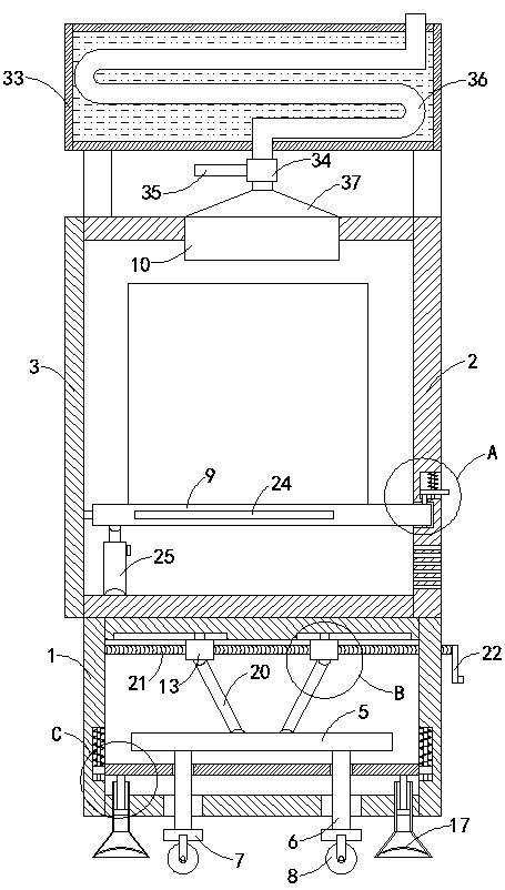
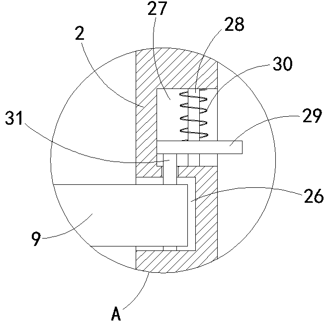
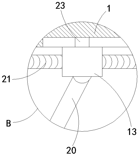
[0030] like Figure 1-7 As shown, an active power filter installed by air pressure adsorption includes a cabinet body 1 and a cabinet body 2 fixedly connected to the upper end of the cabinet body 1, a side door 3 is hinged on the side wall of the cabinet body 2, and the inside of the cabinet body 2 is installed There is a filter device, a movable plate 4 is provided in the box body 1, a reset mechanism for resetting the movable plate 4 is provided on the side wall of the box body 1, a support mechanism is provided at the lower end of the movable plate 4, and the upper side of the movable plate 4 A horizontal plate 5 is provided, the four corners of the lower end of the horizontal plate 5 are fixedly connected with supporting columns 6, the lower ends of the supporting columns 6 are set through the movable plate 4 and the bottom surface of the box body 1, and the lower ends of the supporting columns 6 are fixedly connected with mounting seats 7, The bottom sur...


PUM


Abstract

The invention belongs to the electricity field, and especially relates to an active electric filter in atmospheric adsorptive installation. The active electric filter comprises a tank body and a cabinet body fixedly connected to the upper end of the tank body; a side door is hinged on the sidewall of the cabinet body, filtering equipment is installed in the cabinet body, a movable plate is arranged in the tank body, and a reset mechanism for resetting the movable plate is arranged on the sidewall of the tank body; a support mechanism is arranged at the lower end of the movable plate, a transverse plate is arranged at upper side of the movable plate, and support pillars are fixedly connected with four corners of the lower end of the transverse plate; the lower ends of the support pillars are arranged by penetrating the movable plate and the bottom surface of the tank body, and fixedly connected with an installation base; an opening corresponding to the installation base is arranged on the bottom surface of the tank body, rollers are arranged at the lower end of the installation base, a lifting mechanism for regulating the transverse plate is arranged in the tank body, and an installation plate is slidingly connected in the cabinet body. The active electric filter disclosed by the invention has the advantages that the transportation and the movement of the active electric filterare convenient, the ground cannot be damaged in the installation process, and the equipment in the active electric filter can be conveniently installed and maintained.

Description

technical field [0001] The invention belongs to the field of electric power, in particular to an active power filter installed by air pressure adsorption. Background technique [0002] Active power filter is a new type of power electronic device used to dynamically suppress harmonics and compensate reactive power. It can quickly track and compensate harmonics of different sizes and frequencies. The source LC filter can only passively absorb harmonics of fixed frequency and size. APF can control and actively output the size, frequency and phase of the current by sampling the load current and separating each harmonic and reactive power, and Quick response, offset the corresponding current in the load, realize dynamic tracking compensation, and can not only compensate harmonics but also compensate reactive power and unbalance. [0003] When the existing active power filter is installed, it is generally installed through anchor bolts, and it is necessary to drill holes on the g...

Claims


Application Information

Patent Timeline
IPC IPC(8): H02J3/01H02J3/18H02B1/46H02B1/56H05K7/20
CPCH02B1/565H02B1/52H02J3/01H02J3/18H02B1/46H02B1/505H02B1/54H02B1/28H02B1/48Y02E40/20Y02E40/40Y02E40/30
Inventor 崔宗跃
Owner 国网福建省电力有限公司武平县供电公司
Why Eureka
Try Eureka