
Percutaneous dual-cavity feeding tube

A cannula and outer cannula technology, applied in the field of medical devices, can solve problems such as poor breathing, foreign body sensation in the nasopharynx, and decreased quality of life of patients, and achieve the effect of improving comfort and relieving pain

Pending Publication Date: 2018-10-02
SHANDONG RES INST OF TUMOUR PREVENTION TREATMENT
View PDF0 Cites 0 Cited by
  • Summary
  • Abstract
  • Description
  • Claims
  • Application Information

AI Technical Summary

Problems solved by technology

The traditional feeding tube is inserted into the stomach through the nasal cavity, pharynx, and esophagus. Wearing the tube for a long time may easily cause foreign body sensation in the nasopharynx, poor breathing, nasal mucosal erosion, ulcer formation, etc., and the quality of life of patients will be significantly reduced.

Method used


Image

  • Percutaneous dual-cavity feeding tube
  • Percutaneous dual-cavity feeding tube
  • Percutaneous dual-cavity feeding tube

Examples


Embodiment 1

[0035] Embodiment 1: The anti-backlash structure can be the following structure, which includes a balloon 15 fixed on the outer tube 1 and an inflation tube 16 arranged in the inner hole of the outer tube 1, the tail end of the inflation tube 16 is connected to the balloon 15, The head end of the inflation tube 16 is provided with a one-way valve 17 . When the overtube 1 and the balloon 15 enter the stomach, the inflatable balloon 15 in the balloon 15 is inflated through the inflatable tube 16, so that the overtube 1 is pulled outward to make the balloon 15 drive the anterior wall of the stomach closer to the abdominal wall. Due to the presence of the one-way valve 17, the gas in the balloon 15 can be prevented from overflowing.

Embodiment 2

[0036] Embodiment 2: The anti-backlash structure can be the following structure, which includes a number of baffles 18 arranged at intervals along the circumferential direction on the outer wall of the outer sleeve 1, the front ends of the baffles 18 are fixed to the outer sleeve 1, and the front ends of the baffles 18 are fixed along the axial direction of the outer sleeve 1. Extending to the rear, the blocking piece 18 is in a curved structure, and its tail end is not in contact with the outer wall of the outer sleeve 1 . Because the baffles 18 are bent and their tail ends are not in contact with the overtube 1, when the overtube 1 is inserted into the stomach along the guide wire, each baffle 18 is squeezed and deformed inward and enters the stomach, and when the overtube 1 is pulled outward At this time, because the tail end of the baffle 18 is warped and deformed after contacting the anterior stomach wall, each bending angle increases to realize the open structure, and eac...


PUM


Abstract

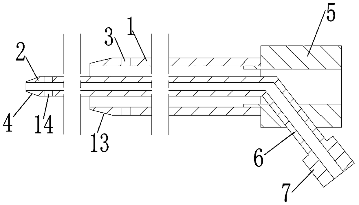
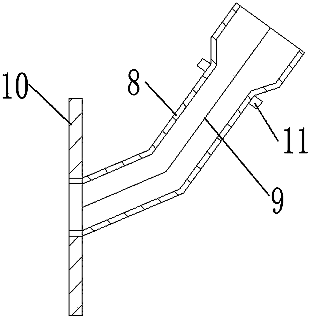
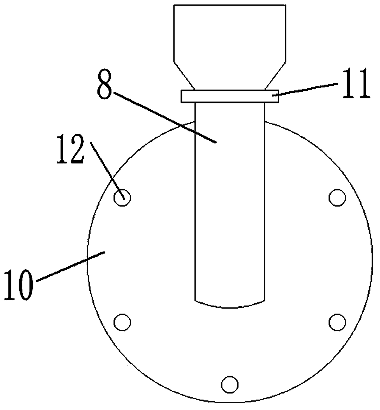
A percutaneous dual-cavity feeding tube includes an outer sleeve, an inner sleeve, connector I, a branch tube, connector II and a fixing device. A puncture pathway is established in the front abdominal wall of a patient according to an endoscopic PEG (percutaneous endoscopic gastrostomy) operation method; the outer sleeve and the inner sleeve are inserted into the stomach under guidance of a wireso as to fix the front gastric wall to the abdominal wall; the inner sleeve is then inserted into the distal duodenum through the pyloric obstruction; the outer sleeve is fixed to the surface skin ofthe abdominal wall of the patient via the fixing device. A syringe can be connected into the connector II to inject a nutrient liquid into the duodenum; the inner end of the outer sleeve is inserted into the stomach; after a vacuum aspirator is connected into the connector I, the vacuum aspirator can be used to draw out gastric contents via a gap between a bore of the outer sleeve and the outer wall of the inner sleeve; since the inner sleeve may slide along the outer sleeve, the position of the inner sleeve is convenient to adjust. Nasal placement of the feeding tube is avoided, so that lesspain is caused to a patient, and comfort of treatment is improved.

Description

technical field [0001] The invention relates to the field of medical instruments, in particular to a percutaneous double-chamber feeding tube. Background technique [0002] Clinically, for patients with pyloric obstruction who are not suitable for surgical treatment, it is generally necessary to place a feeding tube through the nose. While injecting the nutrient solution into the duodenum, it is also necessary to suck out the retained fluid in the stomach. The traditional feeding tube is inserted into the stomach through the nasal cavity, pharynx, and esophagus. Wearing the tube for a long time may easily cause foreign body sensation in the nasopharynx, poor breathing, erosion of nasal mucosa, and ulcer formation, which will significantly reduce the quality of life of patients. Contents of the invention [0003] In order to overcome the deficiencies of the above technologies, the present invention provides a percutaneous double-chamber feeding tube that reduces the pain of...

Claims


Application Information

Patent Timeline
IPC IPC(8): A61J15/00A61M1/00A61M25/00A61M25/10
CPCA61M1/0023A61J15/0023A61J15/0053A61J15/0069A61J15/0073A61M25/0026A61M25/10A61M2025/0039A61M2210/1053A61M2210/1057A61M1/84A61M2210/005
Inventor 牛洪欣汪建郝亮孙文
Owner SHANDONG RES INST OF TUMOUR PREVENTION TREATMENT
Learn More