Plate shearing machine

A technology of shearing machine and baffle mechanism, which is applied in the field of machinery, can solve the problems of affecting the appearance of parts, scratches, and affecting the surface quality of parts, so as to improve the quality of parts, avoid scratches, and prevent rotation

Active Publication Date: 2018-10-02
HUNAN UNIV OF HUMANITIES SCI & TECH
View PDF8 Cites 4 Cited by
  • Summary
  • Abstract
  • Description
  • Claims
  • Application Information

AI Technical Summary

Problems solved by technology

[0003] In the cutting of thin sheets, thin sheets are generally used for outer coverings, such as automobile outer coverings, packaging outer coverings, etc., but scratches during thin sheet cutting are a major problem in production. In order to improve the accuracy of cutting , When feeding, it is necessary to press the sheet material tightly so that it is close to the supporting table to avoid bending or bulging. In this way, when the sheet material passes through the cutting tool, it is easy to cause scratches, which not only affect the appearance of the parts, but also At the same time, scratch defects on the inner surface will cause bulging ribs on the surface of the part when the part is formed, seriously affecting the surface quality of the part

Method used


Image

  • Plate shearing machine
  • Plate shearing machine
  • Plate shearing machine

Examples


Embodiment Construction

[0024] In order to enable those skilled in the art to better understand the technical solution of the present invention, the present invention will be described in detail below in conjunction with the accompanying drawings. The description in this part is only exemplary and explanatory, and should not have any limiting effect on the protection scope of the present invention. .

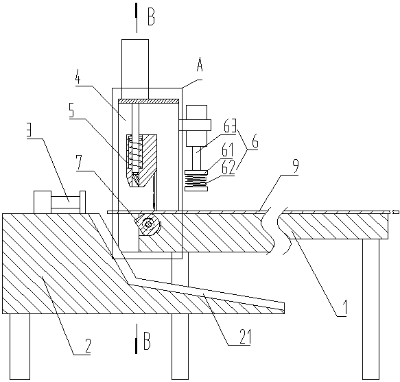
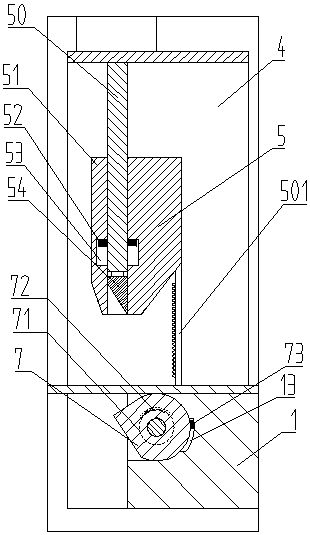
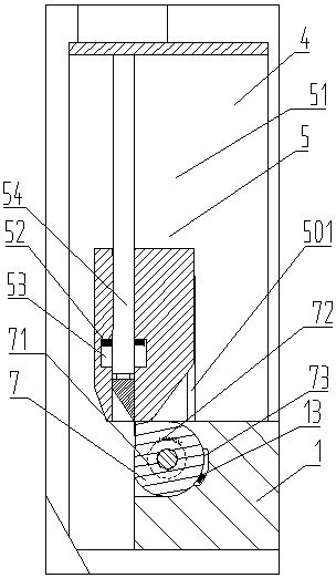
[0025] Such as Figure 1-Figure 5 As shown, the specific structure of the present invention is: a shearing machine, comprising a support base 1 and a baffle seat 2 set apart from the support base 1, the baffle seat 2 is provided with a baffle mechanism 3, the support base 1 and the support A feeder chute 21 is arranged at a distance from the seats 1, and a gantry frame 4 is provided at one end of the support seat 1, and an upper cutter 5 vertically raised and lowered on the surface of the support seat 1 is arranged inside the gantry frame 4. There is a lower cutter 7, and the side of the gantry 4 away...


PUM


Abstract

The invention discloses a plate shearing machine. The machine comprises a supporting base and a baffle seat away from the supporting base; a baffle mechanism is arranged on the baffle seat, a discharging groove is formed between the supporting base and the baffle seat, a portal frame is arranged at one end of the supporting base, a upper tool capable of ascending and descending in a manner of being perpendicular to the surface of the supporting base is arranged in the portal frame, a lower tool is arranged below the upper tool in a matched manner, an elastic clamping plate used for pressing aboard is arranged on the side, away from the baffle seat, of the portal frame, the lower tool is rotatably arranged on the supporting base, a rotating shaft is arranged in the lower tool in a penetrating manner, rotating wheels are arranged on the two ends of the rotating shaft, transmission teeth are arranged on the rotating wheels, and racks matched with the transmission teeth of the rotating wheels are arranged on the two sides of the upper tool. The plate shearing machine effectively prevents the board from being scratched, part quality is improved, and safety property is high.

Description

technical field [0001] The invention belongs to the field of machinery, in particular to a shearing machine. Background technique [0002] The shearing machine is a kind of forging machinery, and its main function is the metal processing industry. Products are widely used in: light industry, aviation, shipbuilding, metallurgy, instrumentation, electrical appliances, stainless steel products, steel structure construction and decoration industries. The shearing machine is often used to cut the blanks with straight edges. The shearing process should ensure the straightness and parallelism of the sheared surface of the sheared sheet, and minimize the distortion of the sheet to obtain high-quality workpieces. [0003] In the cutting of thin sheets, thin sheets are generally used for outer coverings, such as automobile outer coverings, packaging outer coverings, etc., but scratches during thin sheet cutting are a major problem in production. In order to improve the accuracy of cu...

Claims


Application Information

Patent Timeline
Patent Type & Authority Applications(China)
IPC IPC(8): B23D15/06
CPCB23D15/06
Inventor 谭峰亮
Owner HUNAN UNIV OF HUMANITIES SCI & TECH
Why Eureka
Try Eureka