
Sheet conveying and grooving device

A technology of grooving and sheeting, which is applied in the field of grooving device for sheet material conveying, which can solve the problems of poor sheet grooving accuracy, increased device operation and maintenance costs, difficult reciprocating movement of grooving pressure rods, etc., and achieves a reasonable structural design Effect

Inactive Publication Date: 2018-10-02
嘉兴汉羿文化传播有限公司
View PDF0 Cites 4 Cited by
  • Summary
  • Abstract
  • Description
  • Claims
  • Application Information

AI Technical Summary

Problems solved by technology

After the production and processing of the existing panels are completed in the previous process, the sides of the panels need to be grooved to facilitate the connection, assembly and splicing of the panels. In order to meet the needs of later construction and installation, the existing panels need to The plates with longer specifications are cut into plates with smaller sizes according to the needs of use. Therefore, the existing plate grooving process mainly adopts two methods. One method of plate grooving is to cut the plates with longer sizes The plates are cut evenly according to the needs, and then the plates cut into smaller sizes are placed on the grooving mechanism one by one for grooving processing. This method is mainly suitable for blocks with smaller quality and smaller sizes. The grooving process of the plate is convenient for workers to operate, which can ensure the quality of the grooving of the plate. Another method of plate printing is to cut the plate continuously and evenly during the transmission process, and then evenly cut the plate after the grooving process. Cutting, this method is mainly suitable for plates with large sizes and heavy weights, which is not convenient for the plates to be transported, but it is difficult to ensure the quality and accuracy of the grooving of the plates when cutting the plates during the transmission process degree, and the grooving of the plate takes a certain amount of time, so the plate needs to be conveyed intermittently during the conveying process to meet the needs of the plate grooving, and the plate grooving and the intermittent conveying of the plate need to be accurately coordinated, so the numerical control requirements for the whole set of equipment High, which greatly increases the operation and maintenance costs of the device
During the grooving process of the existing grooving mechanism, the sheet-like structure of the plate is difficult to translate smoothly and accurately according to the needs of the grooving process during the grooving process, resulting in poor grooving accuracy of the plate, and It is difficult for the existing grooving pressure rod to reciprocate continuously and stably at high frequency, and it is difficult to adjust the reciprocating translation range and the reciprocating translation position of the grooving pressure rod efficiently and conveniently. The existing grooving pressure rod mainly uses a motor Drive, the motor will produce rotational inertia during the process of stopping the rotation, which will cause unnecessary continuous reciprocating end action of the grooving pressure rod, which will affect the efficiency and quality of the grooving process of the plate, and cannot meet the needs of production and use

Method used


Image

  • Sheet conveying and grooving device
  • Sheet conveying and grooving device
  • Sheet conveying and grooving device

Examples


Embodiment Construction

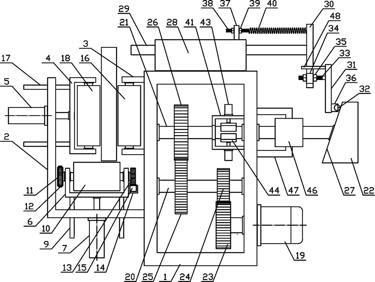
[0015] In order to further describe the present invention, a specific implementation of a sheet conveying and cutting device will be further described below in conjunction with the accompanying drawings. The following examples are explanations of the present invention and the present invention is not limited to the following examples.

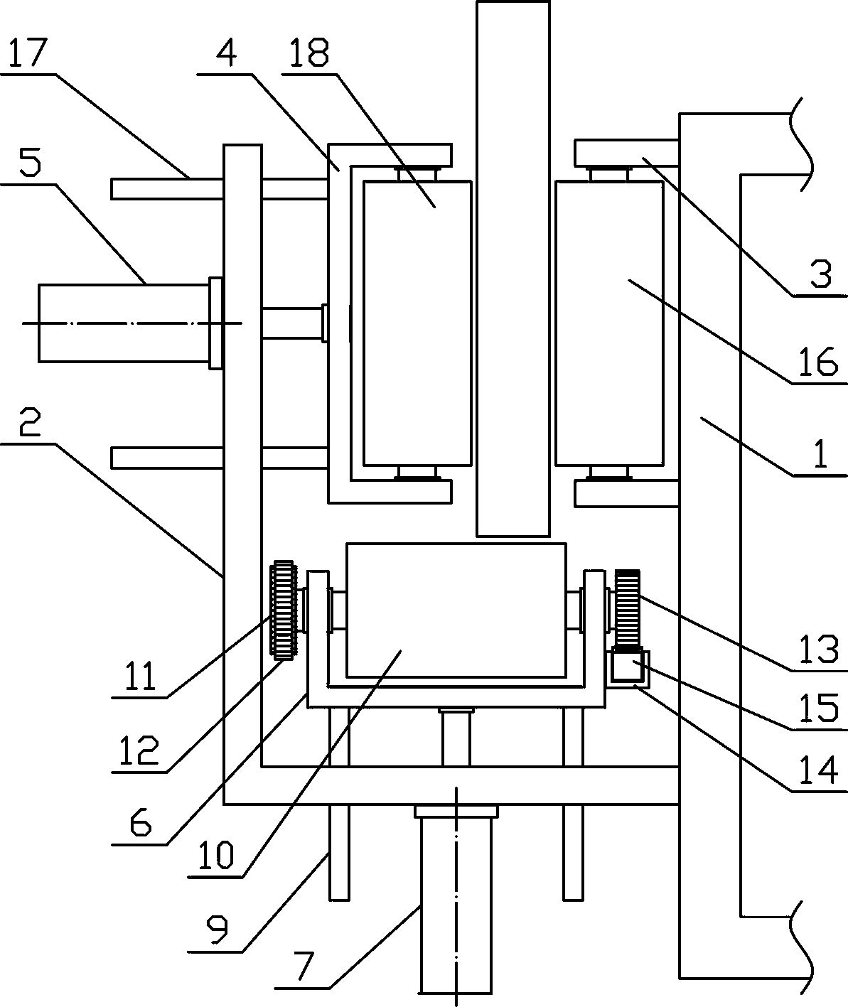
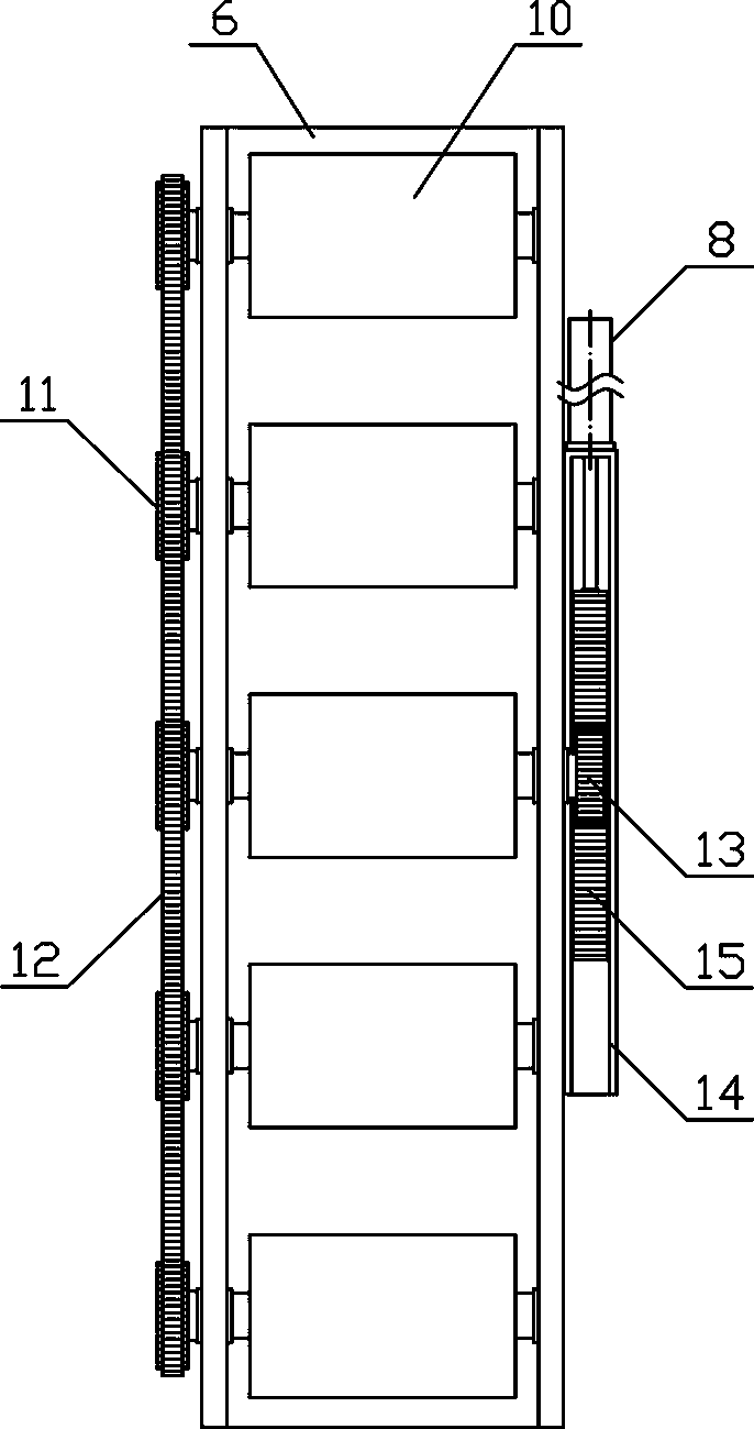
[0016] Such as figure 1 As shown, a sheet material conveying grooving device of the present invention includes a fixed bracket 1, a feeding mechanism, a driving mechanism and a grooving mechanism, the driving mechanism is vertically arranged on the fixing bracket 1, and the feeding mechanism is horizontally arranged on the fixing bracket 1- On the side, the slotting mechanism is horizontally arranged on the upper side of the fixed bracket 1 . Such as figure 2 As shown, the material transmission mechanism of the present invention includes a transmission bracket 2, a material receiving bracket 3, a pressure material bracket 4, a pressure materi...


PUM


Abstract

The invention discloses a sheet conveying and grooving device, and belongs to the field of building material processing machinery and equipment. According to the sheet conveying and grooving device, alifting support is horizontally arranged on the lower side of a conveying support, a plurality of material conveying rotating rollers are sequentially and uniformly arranged on the lifting support inthe horizontal direction, a plurality of material bearing rotating rollers are sequentially and vertically arranged on a material bearing support in the horizontal direction, a plurality of materialpressing rotating rollers are sequentially and vertically arranged on a material pressing support in the horizontal direction, an upper fixing rotating shaft and a lower fixing rotating shaft are sequentially and horizontally connected to a fixing support in a rotating mode from top to bottom, a grooving rotating disc is vertically arranged at one end of the upper fixing rotating shaft, a groovinginclined plane is arranged on one side of the grooving rotating disc, and a grooving pressing rod is arranged on a reciprocating support in a sliding mode in the horizontal direction. According to the sheet conveying and grooving device, the structural design is reasonable, sheets can be stably and accurately conveyed in a translation mode according to requirements, the side edges of the sheets can be continuously subjected to grooving processing in the sheet conveying process, the processing automation degree of the sheets can be improved, and the requirement for processing and using can bemet.

Description

technical field [0001] The invention belongs to the field of building material processing machinery and equipment, and in particular relates to a sheet material conveying and cutting device, which is mainly used in the field of building plate processing machinery and equipment. Background technique [0002] Plate refers to a flat rectangular building material plate processed into a certain size, used as a component of a wall, ceiling or floor, and also refers to a metal plate formed by forging, rolling or casting. According to the material category, it includes metal plate, glass plate And wooden boards, etc., according to the thickness of the board, including thin boards, medium boards, thick boards and special thick boards. During the use of the board, the board needs to be cut, bent, stamped and welded according to the specific use conditions. The wooden board can be processed into building material boards of various shapes and specifications, and the metal board can be p...

Claims


Application Information

Patent Timeline
Patent Type & Authority Applications(China)
IPC IPC(8): B23D79/00B23Q7/00B23Q7/05B27F5/02B28D1/22
CPCB23D79/00B23Q7/005B23Q7/05B27F5/02B28D1/22
Inventor 王英
Owner 嘉兴汉羿文化传播有限公司
Learn More