Light source mask optimization method adopting compression sensing technology

A technology of compressed sensing and optimization method, which is applied in the photo-engraving process of originals, optics, and patterned surfaces for opto-mechanical processing, etc. SO problem optimal solution and other problems

Active Publication Date: 2018-10-02
BEIJING INSTITUTE OF TECHNOLOGYGY
View PDF5 Cites 10 Cited by
  • Summary
  • Abstract
  • Description
  • Claims
  • Application Information

AI Technical Summary

Problems solved by technology

[0007] However, there are two shortcomings in the above method: first, the linear Bregman algorithm used in the above method needs to force the optimization variable of the light source to zero in each optimization process, and this operation will inevitably affect the optimal solution of the SO problem, thus affect the imaging performance of the lithography system; secondly, the above method only considers the application of the linear compressive sensing technology in the light source optimization problem, and does not apply the nonlinear compressive sensing technology to the mask optimization problem, so the final lithography Imaging performance is not yet optimal results
[0008] In summary, the computational efficiency of the traditional SMO method and the SO optimal solution problem based on linear compressed sensing technology need to be further improved and improved.

Method used


Image

  • Light source mask optimization method adopting compression sensing technology
  • Light source mask optimization method adopting compression sensing technology
  • Light source mask optimization method adopting compression sensing technology

Examples


Embodiment

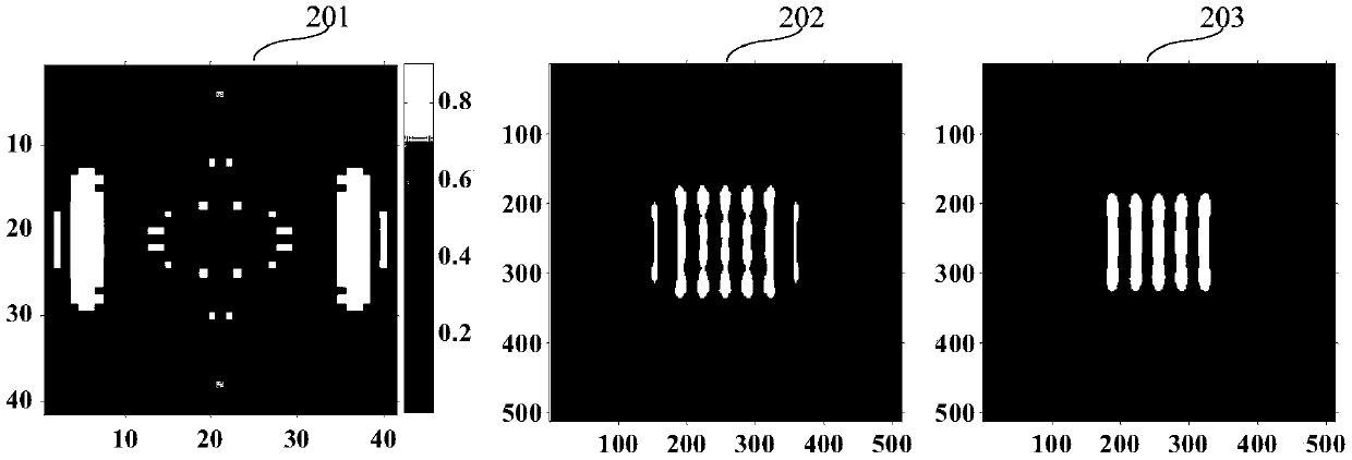
[0063] Such as figure 2 Shown is the optimized light source pattern obtained by the traditional hybrid SMO method, the optimized mask pattern and its imaging in the photoresist at the best focal plane under the rated exposure. 201 is an optimized light source pattern obtained by using the traditional hybrid SMO method, white represents the light-emitting area, and black represents the non-light-emitting area. 202 is a mask pattern obtained by using a traditional hybrid SMO method, white represents an opening region, black represents a light blocking region, and its critical dimension is 45nm. 203 is to use 201 as the light source and 202 as the mask. When the exposure amount change and the defocus effect are not considered, the image is formed in the photoresist at the ideal focal plane, and the imaging error is 2888. The imaging error is defined as the imaging error in the photoresist The square of the Euler distance from the target pattern, the mask complexity is 197, and ...


PUM


Abstract

The invention discloses a light source mask optimization method adopting a compression sensing technology. The light source optimization SO problem is configured into an image recovery problem for solving 2 norm in a non-constraint condition, namely a formula which is as shown in the specification, wherein by virtue of a constraint condition linear equation a formula which is as shown in the specification, the space image corresponding to the optimized light source is close to a target image value as far as possible. In addition, the mask optimization MO problem is configured into image optimization problem comprising a sparse regular term and a low-rank regular item, namely a formula which is as shown in the specification, wherein by virtue of a constraint condition linear equation a formula which is as shown in the specification, the space image observed data corresponding to the optimized mask and light source can be close to graphical observation data as far as possible, a formulawhich is as shown in the specification; by virtue of the constraint condition, the number of equations in the optimization process can be further lowered; a formula which is as shown in the specification; and by virtue of the constraint condition, mask complexity in the optimization process can be lowered as far as possible.

Description

technical field [0001] The invention relates to the technical field of lithographic resolution enhancement, in particular to a light source mask optimization method using compressed sensing technology. Background technique [0002] Optical lithography is the current mainstream lithography technology. It uses the principle of optical projection imaging to transfer the integrated circuit pattern on the mask to the wafer coated with photoresist through step-and-scan exposure. With the rapid development of the semiconductor industry, the feature size of VLSI is also shrinking. The lithography system is the main core equipment in the IC manufacturing industry. The current mainstream lithography technology mainly adopts the deep ultraviolet immersion lithography technology with a light source wavelength of 193nm. [0003] As the lithography technology node enters 45-14nm, the critical dimensions of integrated circuits have entered the deep sub-wavelength range. At this time, the ...

Claims


Application Information

Patent Timeline
Patent Type & Authority Applications(China)
IPC IPC(8): G03F1/00G03F1/70
CPCG03F1/00G03F1/70
Inventor 马旭王志强赵琦乐
Owner BEIJING INSTITUTE OF TECHNOLOGYGY
Why Eureka
Try Eureka