Heat dissipation device for communication equipment

A heat dissipation device and communication equipment technology, which is applied in the construction parts of electrical equipment, cooling/ventilation/heating transformation, electrical equipment shell/cabinet/drawer, etc., which can solve poor heat dissipation, accelerate heat loss, and reduce the temperature of air intake, etc. problems, to achieve the effect of improving the effect of heat dissipation device, improving the effect of shock absorption and noise reduction, and reducing noise and vibration

Active Publication Date: 2018-10-02
新三科技有限公司
View PDF3 Cites 4 Cited by
  • Summary
  • Abstract
  • Description
  • Claims
  • Application Information

AI Technical Summary

Problems solved by technology

The total heat dissipation area of ​​the radiator is small in a limited space, and the thermal resistance of the profile is large, so it is difficult to meet the heat dissipation requirements of high-power modules
Even with a heat sink type structure, often due to poor heat dissipation in a limited space, the heat sink cannot perform well
Additional devices are needed for physical cooling, such as straight condenser tubes to reduce the temperature of the air intake, and then allow air convection inside the device to accelerate heat loss. Therefore, it is urgent to design a heat sink for communication equipment to solve the above problems

Method used


Image

  • Heat dissipation device for communication equipment
  • Heat dissipation device for communication equipment
  • Heat dissipation device for communication equipment

Examples


Embodiment Construction

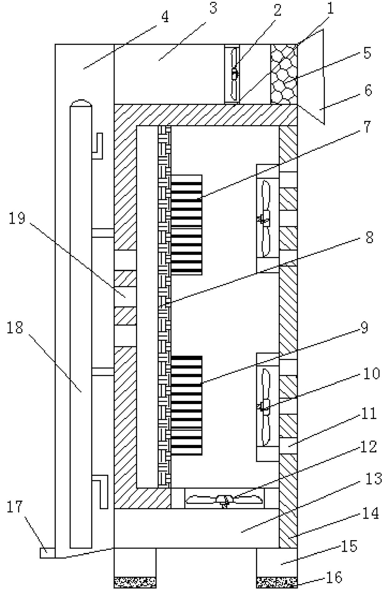
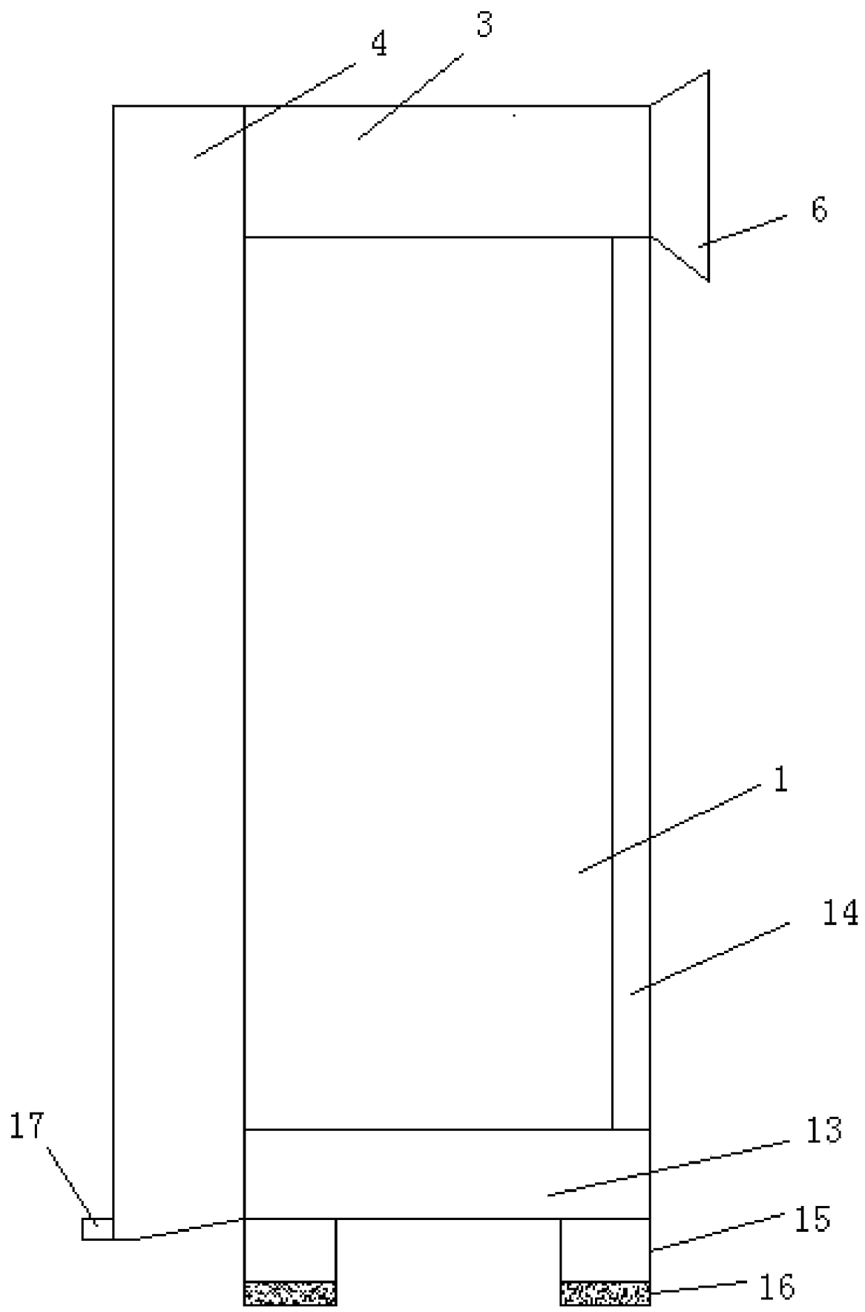
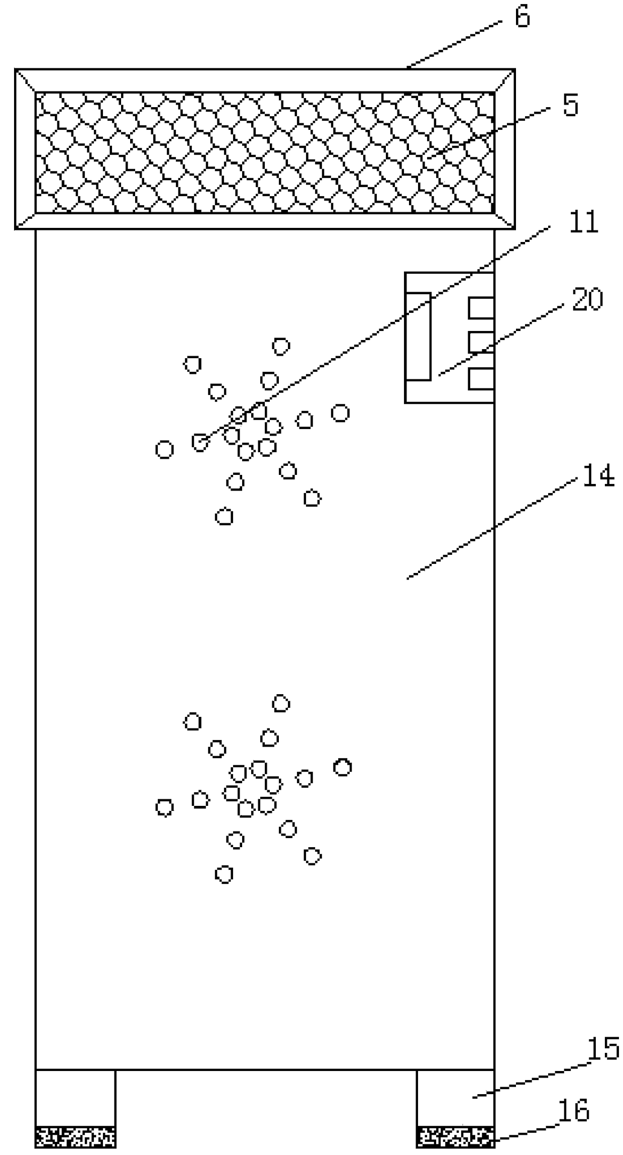
[0022] The following will clearly and completely describe the technical solutions in the embodiments of the present invention with reference to the accompanying drawings in the embodiments of the present invention. Obviously, the described embodiments are only some, not all, embodiments of the present invention.

[0023] refer to Figure 1-3 , a heat dissipation device for communication equipment, comprising a box body 1, a cover plate 14 is fixed to the outer wall of the box body 1 by bolts, and the same chip 8 is fixed to the inner walls of the opposite sides of the box body 1 by bolts, and the outer wall of the chip 8 side is The first radiating fin 7 and the second radiating fin 9 distributed equidistantly are fixed by bolts, the outer wall of one side of the cover plate 14 is fixed with the second fan 10 distributed equidistantly by bolts, and the second fan 10 is connected with the first radiating fin 7 The height is the same as that of the second heat sink 9, and the he...


PUM


Abstract

The invention discloses a heat dissipation device for communication equipment, and the heat dissipation device comprises a box body. An outer wall of one side of the box body is fixedly provided witha cover plate through a bolt, and the inner walls of two opposite sides of the box body are fixedly provided with the same chip through bolts. The outer wall of one side of the chip is fixedly provided with first cooling fins and second cooling fins, distributed at equal intervals, through bolts. The outer wall of one side of the cover plate is fixedly provided with second fans, distributed at equal intervals, through bolts. Moreover, the second fans have the same height as the first and second cooling fins. The outer wall of one side of the cover plate is provided with heat dissipation holeswhich are annularly distributed at equal intervals, and the heat dissipation holes have the same height as the second fans. The outer wall of the top of the box body is welded with an air incoming pipe, and one end of the inner wall of one side of the air incoming pipe is welded with a filter screen. According to the invention, the device can achieve the air convection effect in the box body, improves the effect of the heat dissipation device, quickly reduces the internal temperature of the box body, protects equipment from being damaged by overheating, and generates very small noise and vibration during operation.

Description

technical field [0001] The invention relates to the technical field of heat dissipation, in particular to a heat dissipation device for communication equipment. Background technique [0002] At present, Industrial Communication Device (ICD) refers to the general term of communication equipment installed in a certain area to transmit radio wave information. Mainly divided into wired communication equipment and wireless communication equipment. Wired communication equipment mainly introduces solutions to serial communication on industrial sites, professional bus communication, industrial Ethernet communication and conversion equipment between various communication protocols. Wireless communication equipment is mainly wireless AP, wireless bridge, wireless network card, wireless lightning arrester, antenna and other equipment. [0003] The communication equipment chassis is used to accommodate and install communication equipment. Since the circuit modules of communication equ...

Claims


Application Information

Patent Timeline
Patent Type & Authority Applications(China)
IPC IPC(8): H05K7/20H05K5/02
CPCH05K5/0234H05K7/20181H05K7/20318H05K7/20327
Inventor 郜佩环
Owner 新三科技有限公司
Why Eureka
Try Eureka