Liquid discharging apparatus and circuit substrate

A circuit substrate and liquid technology, applied in printing devices, printed circuits, printed circuits, etc., can solve the problems of undisclosed circuit substrates, cooling components, etc., to achieve efficient cooling components, efficient cooling, reduction of ejection characteristics and product life. the effect of

Inactive Publication Date: 2018-10-09
SEIKO EPSON CORP
View PDF7 Cites 7 Cited by
  • Summary
  • Abstract
  • Description
  • Claims
  • Application Information

AI Technical Summary

Problems solved by technology

[0005] However, the layout of the circuit board for efficiently cooling the cooling member is not disclosed, and the layout of the circuit board may restrict the arrangement of the cooling member.

Method used


Image

  • Liquid discharging apparatus and circuit substrate
  • Liquid discharging apparatus and circuit substrate
  • Liquid discharging apparatus and circuit substrate

Examples


no. 1 approach

[0052] 1.1 Outline of liquid ejection device

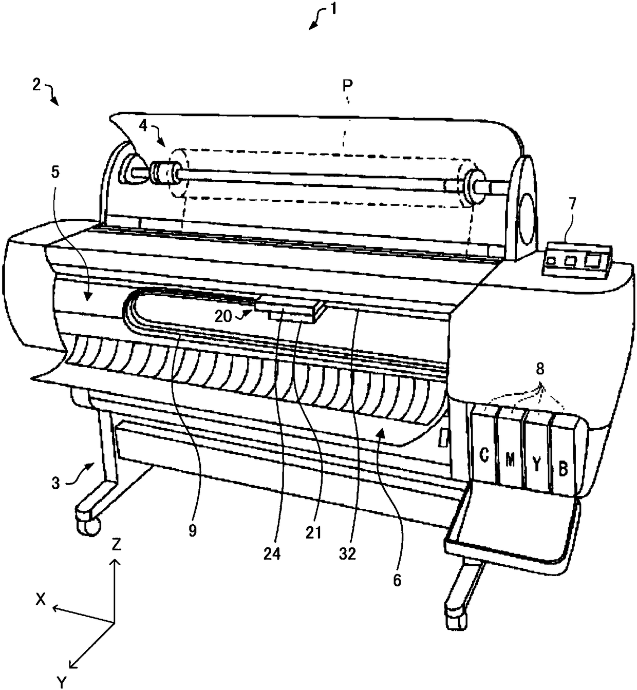
[0053] A printing device as an example of the liquid ejecting device of the first embodiment is an inkjet printer that ejects ink based on image data supplied from an external host computer to form groups of ink dots on a printing medium such as paper, thereby An image (including characters, graphics, etc.) corresponding to the image data is printed.

[0054] In addition, as the liquid ejection device, in addition to printing devices such as printers, for example, a colorant ejection device used in the manufacture of color filters such as liquid crystal displays, organic EL displays, FED (field induced Electrode material discharge devices used in electrode formation such as light-emitting displays), bioorganic substance discharge devices used in biochip production, three-dimensional modeling devices (so-called 3D printers), printing and dyeing devices, etc.

[0055] figure 1 is a schematic diagram of the appearance of the liquid...

no. 2 approach

[0260] The liquid ejection device 1 according to the second embodiment has the same configuration as that of the liquid ejection device 1 according to the first embodiment, except that the layout of the drive signal generation unit 460 of the drive circuit board 420 included in the drive unit 30 is different. . Hereinafter, the content overlapping with the first embodiment will be omitted or simplified, and the content different from the first embodiment will be mainly described.

[0261] Figure 18 It is a schematic diagram showing the layout of the drive circuit board 420 in the second embodiment. also, Figure 18 The direction x, the direction y, and the direction z which are orthogonal to each other are shown and demonstrated in .

[0262] The liquid ejection device 1 according to the second embodiment has the same configuration as that of the liquid ejection device 1 according to the first embodiment, and its illustration and description are omitted ( figure 1 ). In ...


PUM


Abstract

The invention a liquid discharging apparatus which can reduce configuration constrains of a cooling component so as to enable the configuration freedom degree of the cooling component to be higher ina circuit substrate with a drive circuit. The liquid discharging apparatus includes a print head that has a driving element and discharges a liquid when a drive signal is applied and the driving element is driven, a drive signal generation circuit that generates the drive signal based on a drive signal generation control signal for controlling generation of the drive signal, and a drive circuit substrate on which the drive signal generation circuit is provided. The drive circuit substrate has an input connector that inputs the drive signal generation control signal into the drive circuit substrate and an output connector that outputs the drive signal from the drive circuit substrate. A distance between the input connector and the output connector is shorter than a distance between the drive signal generation circuit and the input connector. The distance between the input connector and the output connector is shorter than a distance between the drive signal generation circuit and the output connector.

Description

technical field [0001] The present invention relates to a liquid ejection device and a circuit board. Background technique [0002] A device using a piezoelectric element (for example, a piezo element) is known as a liquid ejection device such as an inkjet printer that ejects ink to print an image or a document. Piezoelectric elements are provided corresponding to a plurality of nozzles in the head (print head), and are driven according to driving signals, so that a predetermined amount of ink (liquid) is ejected from the nozzles at predetermined timings to form dots. The piezoelectric element is a capacitive load such as a capacitor from an electrical point of view, and thus a sufficient current needs to be supplied to operate the piezoelectric element of each nozzle. Therefore, in the liquid ejection device described above, the drive circuit supplies the drive signal amplified by the amplifier circuit to the head to drive the piezoelectric element. [0003] Patent Docume...

Claims


Application Information

Patent Timeline
Patent Type & Authority Applications(China)
IPC IPC(8): B41J2/14B41J29/377
CPCB41J2/14B41J29/377B41J2/04541B41J2/04515B41J2/04548B41J2/0458B41J2/04581B41J2/04588B41J2/15H05K1/0203H05K2201/066
Inventor 伊东祐弘浅川正志平松和宪
Owner SEIKO EPSON CORP
Why Eureka
Try Eureka