Pan-tilt assembly of multi-rotor unmanned aerial vehicle

A multi-rotor unmanned and unmanned aerial vehicle technology, which is applied in the directions of rotorcraft, aircraft parts, unmanned aerial vehicles, etc., can solve the problems of complex gimbal structure, unstable shooting, etc. Easy to carry and transport

Pending Publication Date: 2018-10-09
GUANGZHOU WALKERA TECH CO LTD
View PDF6 Cites 2 Cited by
  • Summary
  • Abstract
  • Description
  • Claims
  • Application Information

AI Technical Summary

Problems solved by technology

[0008] The purpose of the present invention is to provide a multi-rotor unmanned aerial vehicle platform assembly, which is used to solve the problems of complex structure and unstable shooting in the prior art.

Method used


Image

  • Pan-tilt assembly of multi-rotor unmanned aerial vehicle
  • Pan-tilt assembly of multi-rotor unmanned aerial vehicle
  • Pan-tilt assembly of multi-rotor unmanned aerial vehicle

Examples


Embodiment

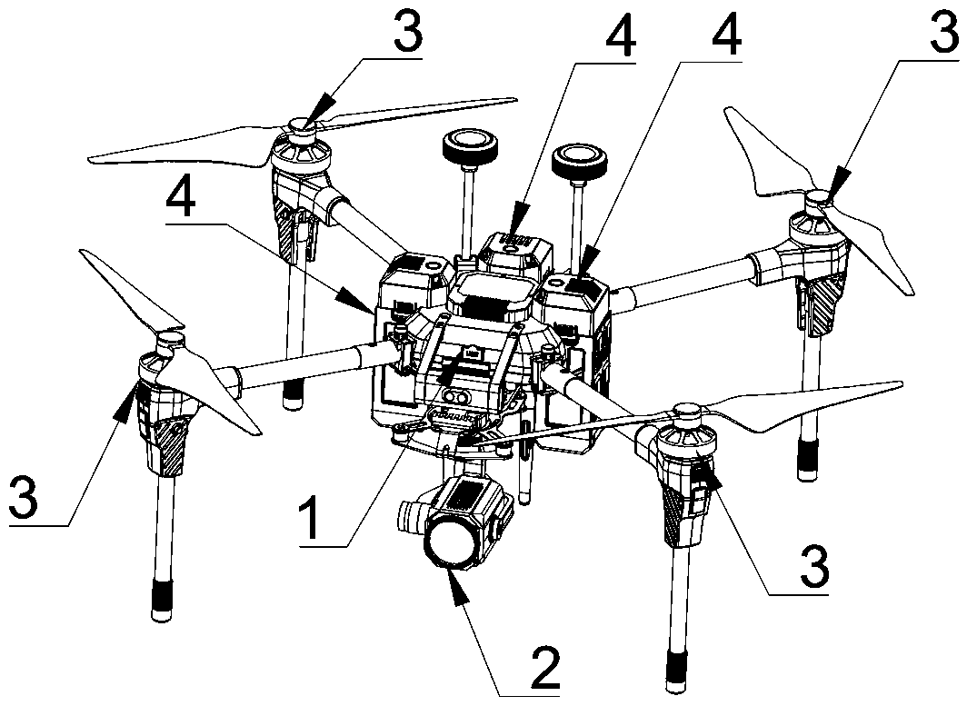
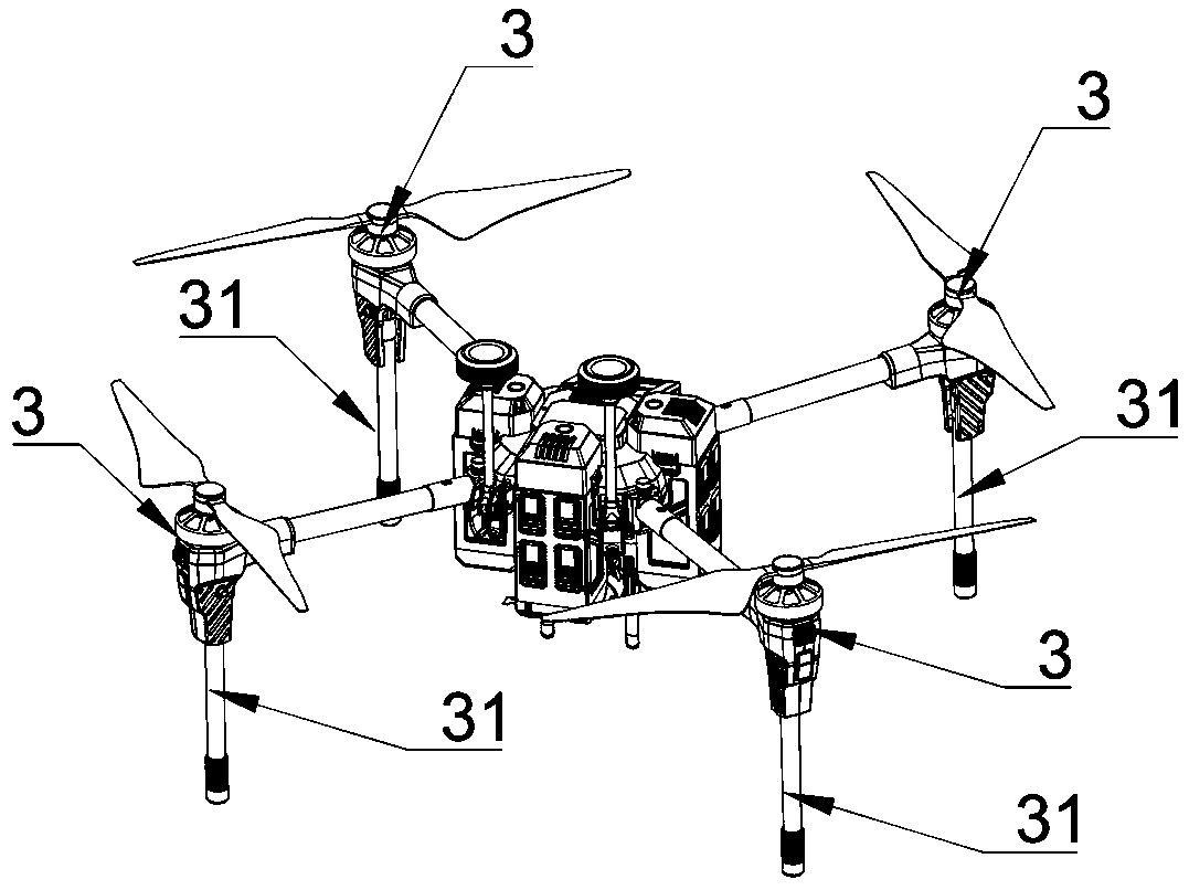
[0049] The invention provides a multi-rotor unmanned aerial vehicle platform assembly, such as figure 1 As shown, the UAV includes a fuselage 1, and the fuselage 1 includes a front side, a rear side, a left side and a right side, and the front side of the fuselage is provided with a pan-tilt assembly 2, and the left side of the fuselage A group of foldable rotor assemblies 3 are respectively provided at the front and rear ends of the fuselage, and two groups of foldable rotor assemblies 3 are provided at symmetrical positions on the right side and the left side of the fuselage.

[0050] The fuselage 1 is approximately in the shape of a cube, including four sides, wherein the front side is provided with a mounting position for the pan-tilt assembly 2, and the pan-tilt assembly 2 is located in the mounting position, and the interior of the fuselage is provided with a control system, As well as circuit components, the control system can be connected through an external remote con...


PUM


Abstract

Disclosed is a pan-tilt assembly of a multi-rotor unmanned aerial vehicle. The multi-rotor unmanned aerial vehicle comprises a fuselage. The fuselage comprises the front side, the rear side, the leftside and the right side; the pan-tilt assembly is arranged on the front side of the fuselage; a foldable rotor assembly is arranged at each of the front end and the rear end of the left side of the fuselage, and two foldable rotor assemblies are arranged on the positions, symmetrical to the left side, of the right side of the fuselage; the pan-tilt assembly comprises a buffer base, a connecting bracket and a camera which are connected sequentially; and the buffer base is connected with the bottom of the front side of the fuselage, the connecting bracket is rotatably connected with the buffer base, and the camera is rotatably connected with the connecting bracket. The overall structure of the pan-tilt assembly is simplified, only the buffer base, the connecting bracket and the camera are arranged as necessary parts of the pan-tilt assembly, wherein the buffer base mainly plays a role in buffering, and the stability of shooting of the unmanned aerial vehicle is greatly improved by adopting shock absorption materials and shock absorption parts.

Description

technical field [0001] This patent relates to the field of multi-rotor drones, specifically, a multi-rotor drone platform assembly. Background technique [0002] The pan / tilt is simply a supporting device for installing and fixing the camera / video camera. It is divided into two types: fixed and electric pan / tilt. [0003] Most of the general drones used are fixed aerial photography gimbals, which are vertically facing the ground to shoot. When consumer drones first came out, most of the aerial photography gimbals used were also fixed gimbals. The camera and the aircraft were fixed on the ground. At the same time, by adjusting the angle of the aircraft and adjusting the angle of view during aerial photography, the advantages of fixed gimbals are that they can reduce costs, reduce weight, and save power, thereby improving flight time; the disadvantages are also very obvious, that is, the quality of aerial photography is poor and cannot be changed. perspective. [0004] When ...

Claims


Application Information

Patent Timeline
Patent Type & Authority Applications(China)
IPC IPC(8): B64D47/08B64C1/30B64C27/08
CPCB64C1/30B64C27/08B64D47/08B64U10/10
Inventor 罗之洪李奔夏烨罗强
Owner GUANGZHOU WALKERA TECH CO LTD
Why Eureka
Try Eureka