Movable vertical-lifting ice drilling device and method

A vertical lifting, ice drilling technology, applied in drilling equipment and methods, drilling equipment, ice drilling and other directions, can solve the problems of inability to drill, difficulty in drilling to meet the aperture standard and depth requirements, and high cost, Achieve the effect of fully automatic operation, avoiding low ice drilling efficiency, and simple installation and production

Pending Publication Date: 2018-10-09
松辽水利委员会水文局黑龙江中游水文水资源中心
View PDF20 Cites 3 Cited by
  • Summary
  • Abstract
  • Description
  • Claims
  • Application Information

AI Technical Summary

Problems solved by technology

At present, artificial ice drilling is mostly used for hydrological surveys during the winter freezing period, which has the problems of high labor intensity, time-consuming and labor-intensive work, and potential safety hazards; Influenced by factors such as the length of the drill pipe and the strength of the blade, it is not possible to drill enough large and deep ice holes at one time with this type of equipment. At the same time, the operation of the equipment is semi-automatic, that is, a large number of manual operations are still required during operation, and there are still problems. Large security risks, limitations on future test development
[0004] At present, due to the large size of the existing large-scale ice drilling machines, it is impossible to drill holes on some ice surfaces with complex conditions (such as roadless, steep slopes, trapezoidal roads, etc.), and it is inconvenient to move and operate, and the cost is high; while small hand-held drills The ice machine cannot be fully automated, and the drilling is difficult to meet the hole diameter and depth requirements

Method used


Image

  • Movable vertical-lifting ice drilling device and method
  • Movable vertical-lifting ice drilling device and method
  • Movable vertical-lifting ice drilling device and method

Examples


Embodiment Construction

[0037] The embodiments of the present invention will be described in further detail below in conjunction with the drawings and examples. The following examples are used to illustrate the present invention, but cannot be used to limit the scope of the present invention.

[0038] In the description of the present invention, unless otherwise specified, "plurality" means two or more. The terms "upper", "lower", "left", "right", "inner", "outer", "front end", "rear end", "head", "tail", etc. indicate the orientation or positional relationship: Based on the orientation or positional relationship shown in the drawings, it is only for the convenience of describing the present invention and simplifying the description, rather than indicating or implying that the device or element referred to must have a specific orientation, be constructed and operated in a specific orientation, and therefore cannot be understood To limit the present invention.

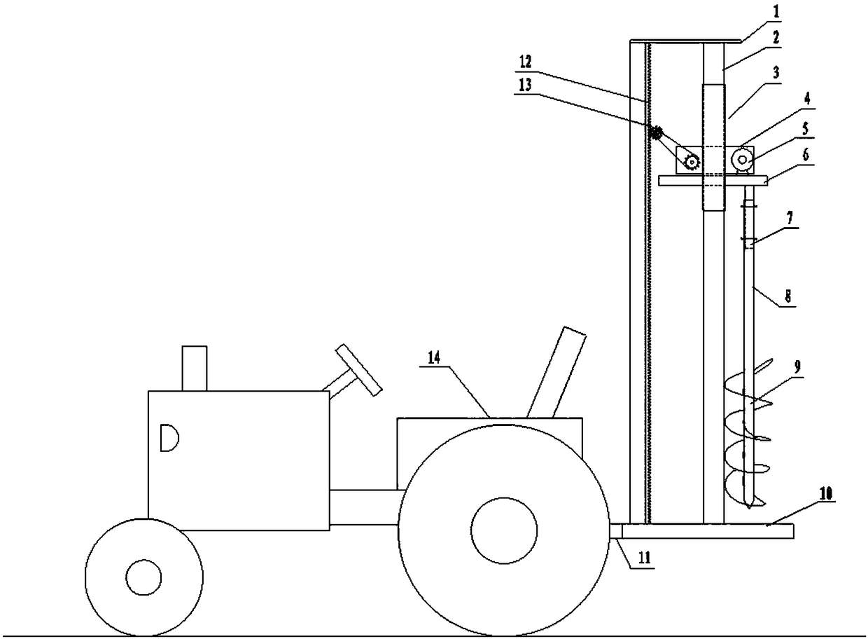
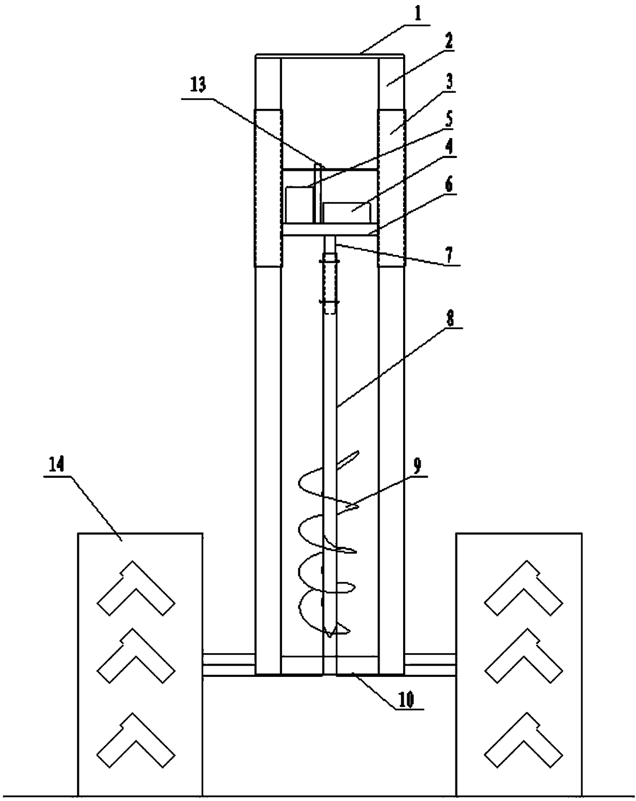
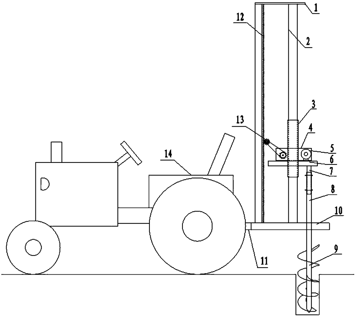
[0039] Such as Figure 1 ~ Figure 4 As sh...


PUM


Abstract

The invention relates to the technical field of ice drilling devices, in particular to a movable vertical-lifting ice drilling device and method. A moving platform of the ice drilling device is connected to the rear portion of a moving vehicle in a lifting mode, a drilling rod is vertically mounted on the moving platform, and the moving platform can drive the drilling rod to move vertically when rising and falling. A drilling rod transmission mechanism is mounted on the moving platform. An output shaft of the moving vehicle is connected with the drilling rod through the drilling rod transmission mechanism. The drilling rod transmission mechanism is used for converting power output by the moving vehicle into potential energy and then converting the potential energy into kinetic energy againunder driving of power of the output shaft, so that the power is provided for rotating of the drilling rod, a drilling bit is driven to rotate, and accordingly efficient ice drilling and perforatingoperation is achieved. According to the movable vertical-lifting ice drilling device and method, it can be guaranteed that the drilling precision is high, the device is moved conveniently, full-automatic operation can be achieved, vertical rising and falling of the drilling rod can be guaranteed strictly, and accordingly the problems that the drilling rod is bent, consequently, the ice drilling efficiency is low and the requirement for the depth is not met are avoided.

Description

Technical field [0001] The invention relates to the technical field of ice drilling equipment, in particular to a movable vertical lifting ice drilling equipment and an ice drilling method. Background technique [0002] The hydrometry system (hydrometry) is the general term for various technical tasks for collecting and sorting hydrological data. Through hydrological tests, data of various hydrological elements can be obtained, so as to generate comprehensive conclusions through data analysis and calculation, and to evaluate and rationalize water resources. Development and utilization, and provide a favorable basis for the planning, design, construction, management and operation of project construction, flood prevention and drought resistance. [0003] The hydrological test during the freezing period in winter requires drilling holes in the frozen layer of the water surface. At present, the hydrological test during the freezing period in winter mostly uses artificial ice piercing,...

Claims


Application Information

Patent Timeline
Patent Type & Authority Applications(China)
IPC IPC(8): E21B7/00E21B7/02E21B15/00E21B19/086E21B19/083E21B17/22
CPCE21B7/008E21B7/026E21B15/003E21B17/22E21B19/083E21B19/086
Inventor 刘国忠吴高庄周艳军梁秀昉张立刚张思禹邱天尧乔铂纯陈晨宋侠飞
Owner 松辽水利委员会水文局黑龙江中游水文水资源中心
Why Eureka
Try Eureka