
Platelet aggregative function detecting system and method

A technology for platelet aggregation and functional testing, applied in the field of medical testing, can solve problems such as long time-consuming, unstable test results, poor repeatability of test results, etc.

Inactive Publication Date: 2018-10-09
CLINDIAG SYSTEMS CO LTD
View PDF8 Cites 3 Cited by
  • Summary
  • Abstract
  • Description
  • Claims
  • Application Information

AI Technical Summary

Problems solved by technology

There are many methods for platelet function testing. These methods have problems such as cumbersome operation, unstable test results, long time consumption, large blood consumption, and poor repeatability of test results. Therefore, platelet function testing is difficult to be widely used in clinical practice.

Method used


Image

  • Platelet aggregative function detecting system and method
  • Platelet aggregative function detecting system and method
  • Platelet aggregative function detecting system and method

Examples


Embodiment 1

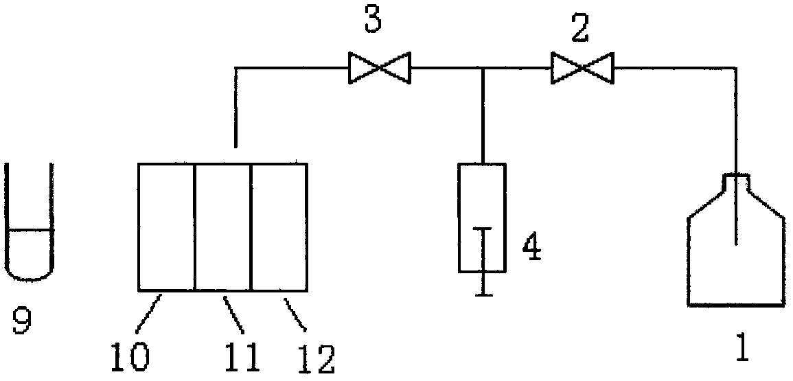
[0056] like figure 1 , in this embodiment, the working principle of the sample suction and transfer unit: put the special detection card on the detection card position of the platelet aggregation function analyzer, close the first valve 2, open the second valve 3, pull down the first syringe 4, and the instrument The sample aspirating needle draws an equal amount of sample from the sample tube 9 into the syringe 4, then the aspirating needle is transferred to the top of the test card, and the syringe 4 is pushed up to transfer the equal amount of sample to the control tube 10, the first detection tube 11 and the second In the detection tube 12, then turn on the mixing motor under the detection card position, and mix the blood samples in the control tube and the detection tube on the detection card respectively;

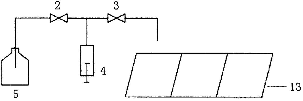
[0057] The cleaning needle is transferred to the top of the cleaning pool, the first valve 2 is opened, the second valve 3 is closed, the syringe is pulled down, the ...

Embodiment 2

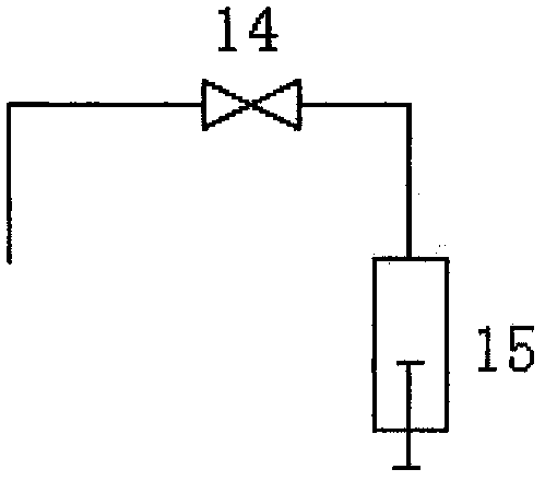
[0061] like image 3 , in this embodiment, the instrument is not provided with a cleaning solution bottle, but is provided with a cleaning pool. When the needle is cleaned, the sampling needle is transferred to the cleaning pool, the third valve 14 is opened, the second syringe 15 is pulled down, and the sampling needle is removed from the cleaning pool. Aspirate the cleaning water, then transfer the sampling needle to the top of the waste liquid collector, push up the second syringe, and discharge the cleaning water to the waste liquid collector.

Embodiment 3

[0063] The instrument reads 450 platelets out of 10,000 red blood cells in the smear area without aggregation inducer, and then reads 40 platelets out of 10,000 red blood cells in the smear area added with inducer, according to the formula

[0064]

[0065] The calculated platelet aggregation rate was 91%.


PUM


Abstract

The invention provides a platelet aggregative function detecting system and method, wherein the system comprises a detecting card, a detecting card position, a sample sucking and transferring unit, acolouring agent adding unit, a smearing unit, a cleaning unit, a micro-scanning unit, an image processing unit and a control unit. The micro-scanning unit is used for microscopic examination of a smear, and each focused field of view is subjected to multiple successive axial scans to obtain clear images of unclear local and individual targets; and the image processing unit is used for processing ascanned image and performing cell identification, classification and counting according to the integrated clear images. The detecting system smears blood samples before and after the addition of an aggregating agent to the same blood sample separately for the microscopic examination, and comprises the number and the volume of platelets and platelet aggregates in the blood samples before and afterthe addition of the aggregating agent to obtain a level of aggregation function of the blood samples under the action of different attracting agents. The detecting system is simple in operation, lowin failure rate, accurate in result and less in consumption of consumable reagents, and is not easily interfered by external factors.

Description

technical field [0001] The invention relates to the technical field of medical testing, in particular to a platelet aggregation function detection system and method. Background technique [0002] The level of platelet function is closely related to the occurrence of thrombus, and the detection of platelet function has important clinical value for the early warning of thrombosis risk and the guidance of antiplatelet therapy. There are many methods for platelet function testing. These methods have problems such as cumbersome operation, unstable test results, long time consumption, large blood consumption, and poor repeatability of test results. Therefore, platelet function testing is difficult to be widely used in clinical practice. Contents of the invention [0003] Purpose of the invention: The technical problem to be solved by the present invention is to provide a platelet aggregation function detection system and method for the deficiencies of the prior art. [0004] In...

Claims


Application Information

Patent Timeline
IPC IPC(8): G01N33/49
CPCG01N33/49
Inventor 徐新董自权詹小勇周强李晓兰郭敏
Owner CLINDIAG SYSTEMS CO LTD
Learn More