
Method for calibrating Tau curve of hollow coil sensor

A technology of hollow coil and calibration method, which is applied in the direction of instruments, measuring devices, and measuring electrical variables, etc., which can solve the problems of inapplicability to solve the transfer function of the receiving coil, complicated process, and low accuracy of the numerical solution of the induced voltage curve.

Active Publication Date: 2018-10-09
CHONGQING UNIV +1
View PDF3 Cites 2 Cited by
  • Summary
  • Abstract
  • Description
  • Claims
  • Application Information

AI Technical Summary

Problems solved by technology

This scheme involves the measurement and calculation of system parameters. Due to measurement errors, the accuracy of numerically solving the induced voltage curve is not high. Considering the interference inside the calibration system, especially the influence of eddy currents induced in low-resistivity soils on the measured voltage is unavoidable. When neglected, the induced voltage curve is difficult to obtain through numerical calculation, so this scheme is not suitable for solving the transfer function of the receiving coil
[0007] In short, the reliability of the induced voltage reconstruction results has not yet been resolved, so many scholars try to reduce the influence of the transition process on the induced voltage by optimizing the size and structure of the coil to be corrected [7-11], which is a conservative strategy , and it is necessary to establish a test method to verify the optimization effect of the coil, the process is complicated

Method used

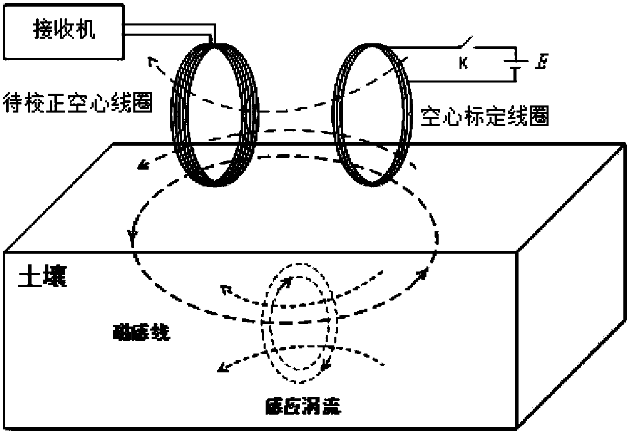
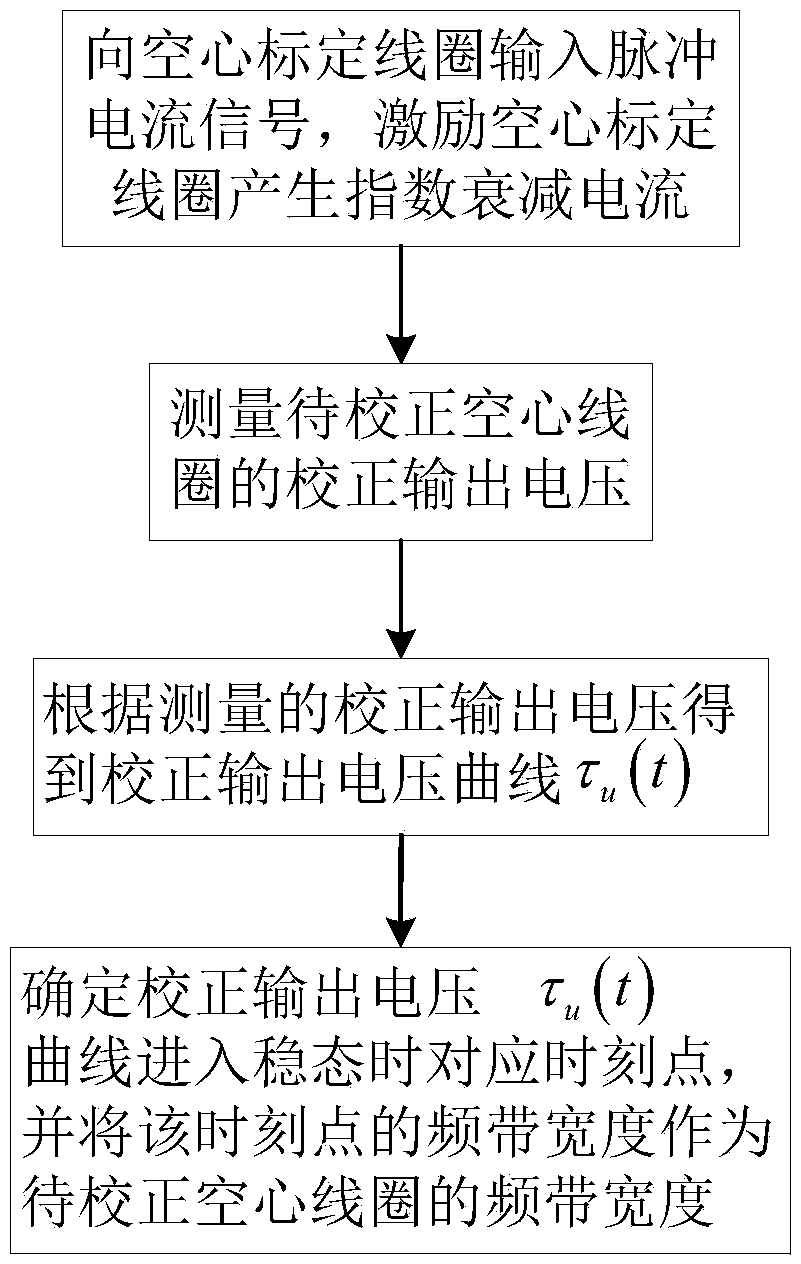

Image

  • Method for calibrating Tau curve of hollow coil sensor
  • Method for calibrating Tau curve of hollow coil sensor
  • Method for calibrating Tau curve of hollow coil sensor

Examples


Embodiment Construction

[0104] The specific implementation manner and working principle of the present invention will be further described in detail below in conjunction with the accompanying drawings.

[0105] A method for calibrating a τ curve of an air-core coil sensor, comprising:

[0106] Steps for building a calibration system;

[0107] combine figure 2 It can be seen that the calibration system includes an air-core calibration coil and two air-core coils to be calibrated, and the two air-core coils to be calibrated are respectively: the first air-core coil to be calibrated and the second air-core coil to be calibrated. The hollow calibration coil is connected to both ends of the DC power supply, and a control switch is connected to the connection line between the DC power supply and the hollow calibration coil; the two ends of the hollow coil to be corrected are connected to the receiver.

[0108] For small air-core coils to be calibrated, the air-core calibration coil and the air-core coil...


PUM


Abstract

The invention discloses a method for calibrating the tau curve of a hollow coil sensor. The method comprises the steps of building a calibration system, wherein the calibration system comprises a hollow calibration coil and at least one hollow coil to be corrected; the hollow calibration coil is connected to the power supply, and the hollow coil to be corrected is connected to a receiver; sendinga pulse current signal to the hollow calibration coil; measuring the frequency band width of the hollow coil to be corrected through a calibration system; calibrating the transfer function H (s) of the hollow coil to be corrected through the calibration system. The method has the beneficial effects that the duration time of the transition process is marked by means of the non-steady-state intervalof the tau curve, and the quantitative measurement of the frequency band width of the coil can be realized, and the characteristic quantity of the result is easy to extract; according to the method,the calibration of the coil transfer function does not depend on the data of the calibration current, so that system parameters such as mutual inductance do not need to be acquired, and the error canbe reduced, and the device is suitable for on-site operation; the to-be-corrected hollow coil can be rapidly calibrated, and the accuracy is high.

Description

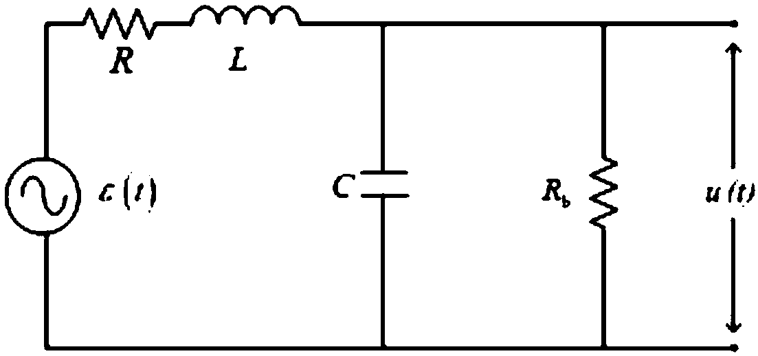
technical field [0001] The invention relates to the technical field of a processing method for an air-core coil transition process, in particular to a method for calibrating a τ curve of an air-core coil sensor. Background technique [0002] Multi-turn air-core coil is one of the important tools to realize mutual conversion of electric field and magnetic field. The relationship between the induced voltage and the actual magnetic field strength can be determined according to the principle of electromagnetic induction. Magnetic field sensors based on air-core coils are widely used in various measurement fields, such as Rogowski Coil, Capacitive Voltage Transformer (CVT), Tesla transformer and transient electromagnetic sensors. Due to the existence of inductance and distributed capacitance, the output voltage u(t) of the coil cannot accurately follow the sudden induced voltage ε(t), which makes the received early signal distorted. This phenomenon is called the transition proce...

Claims


Application Information

Patent Timeline
IPC IPC(8): G01R35/00
CPCG01R35/00
Inventor 付志红王浩文王耀廖先刘龙欢王维李军强
Owner CHONGQING UNIV
Learn More