
Wood machining device

A processing device and wood technology, applied to wood processing equipment, manufacturing tools, bark, etc., can solve problems such as uneven force, trouble, and incomplete circulation of wood, and achieve the effect of smooth removal

Inactive Publication Date: 2018-10-12
YUQING COUNTY XINGDA FURNITURE MFG
View PDF8 Cites 3 Cited by
  • Summary
  • Abstract
  • Description
  • Claims
  • Application Information

AI Technical Summary

Problems solved by technology

However, this single-drum rotating structure is prone to dead angles in the peeling box, especially when multiple logs are put in or the diameter of the logs is small, the wood cannot be completely circulated, so the force is uneven and the peeling effect is poor.
[0004] In order to improve the peeling effect, a blade type peeling machine is usually used now, which peels the rotating log through a scraper, but for the wood with a curved trunk, the peeling effect is poor, and because most of the wood There are many branches, and the damage to the scraper is relatively large during the rotary peeling process. At the same time, the wood needs to be cut and segmented after peeling, which is very troublesome.

Method used


Image

  • Wood machining device
  • Wood machining device
  • Wood machining device

Examples


Embodiment Construction

[0023] Further detailed explanation through specific implementation mode below:

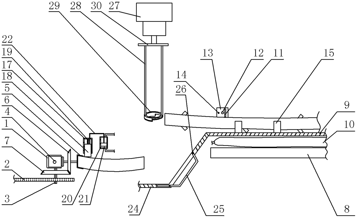
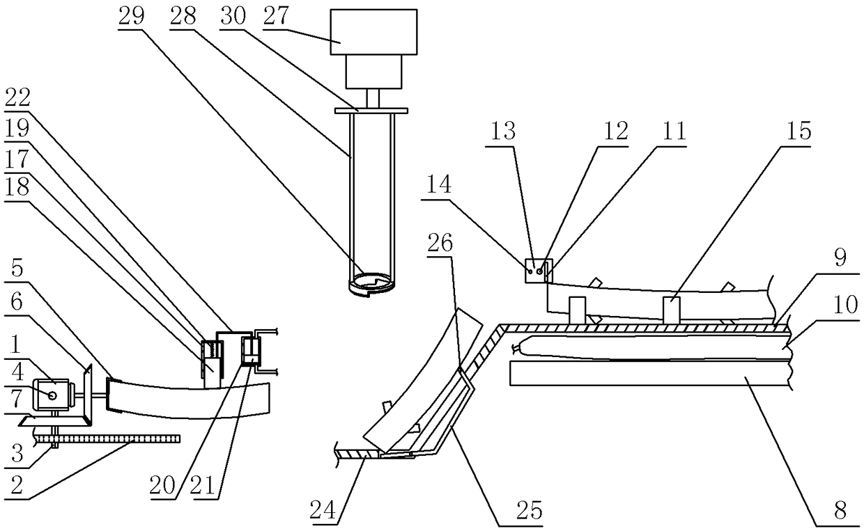
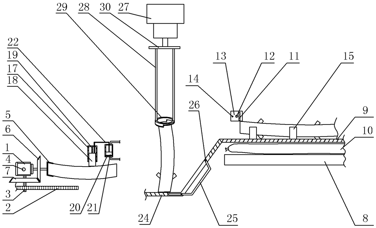
[0024] The reference signs in the accompanying drawings of the description include: the second servo motor 1, the rack 2, the gear rod 3, the support rod 4, the clamping claw 5, the first bevel gear 6, the second bevel gear 7, the support platform 8, the support Plate 9, air bag 10, cutting saw 11, screw rod 12, nut seat 13, limit rod 14, limit plate 15, first servo motor 16, slide rail 17, peeling knife 18, spring 19, pipe body 20, piston 21 , connecting rod 22, the second delimbing edge 23, receiving plate 24, vertical turning bar 25, arc block 26, cylinder 27, stamping bar 28, delimbing knife 29, stamping plate 30, the first delimming edge 31.

[0025] Such as figure 1 In the wood processing device shown, a cutting mechanism, a delimbing mechanism, a peeling mechanism and a transfer mechanism are sequentially arranged on the frame from right to left.

[0026] The transfer mechanism includes ...


PUM


Abstract

The invention relates to field of wood machining, in particular to a wood machining device which comprises a cutting mechanism, a branch removing mechanism, a peeling mechanism and a transferring mechanism. The cutting mechanism comprises a supporting unit and a cutting unit. The supporting unit comprises a supporting table, a supporting plate and an airbag. The cutting unit comprises a screw rod,a nut base and a cutting saw. The peeling mechanism comprises a peeling unit and a gas generating unit. The peeling unit comprises a sliding rail, a peeling cutter and a spring. The gas generating unit comprises a connecting rod, a piston and a pipe body. The two ends of the pipe body communicate with the airbag. The branch removing mechanism comprises a receiving plate, a vertical rotating rod and a branch removing unit. The branch removing unit comprises a stamping rod, a branch removing cutter and an air cylinder. One end of the stamping rod is fixedly connected with an output shaft of theair cylinder, and the other end of the stamping rod is hinged to the branch removing cutter. By the adoption of the technical scheme, bent wood can be peeled conveniently.

Description

technical field [0001] The invention relates to the field of wood processing, in particular to a wood processing device. Background technique [0002] Most of the school desks are now made of particle board, which is also called particle board, particle board, and bagasse board. It is more economical and applicable. The bark stripped from the wood is one of the important raw materials for processing particle board. [0003] The traditional wood peeling machine is mainly a single-drum type. The log rotates and rolls continuously following the rolling of the drum. The hide is discharged from the discharge port on the top of the drum, and the peeled logs are discharged from the discharge port at one end of the drum. But this single drum type rotating structure is very easy to produce dead angle in the peeling box, especially when putting in many logs or the diameter of the log is small, the wood can not be fully circulated, so the stress is uneven and the peeling effect is rel...

Claims


Application Information

Patent Timeline
Patent Type & Authority Applications(China)
IPC IPC(8): B27L1/00B27B13/00B27B13/16
CPCB27B13/00B27B13/16B27L1/005
Inventor 童友华毛国富陈昌禄范厚邦
Owner YUQING COUNTY XINGDA FURNITURE MFG
Learn More