Sewage treatment device with stirring roller being replaced conveniently

A sewage treatment device and stirring roller technology, which is applied in water/sewage treatment, oxidized water/sewage treatment, water/sludge/sewage treatment, etc., can solve the problem that the inside of the device cannot be separated from the water inlet pipe, and it is inconvenient to replace the stirring roller , low filtration efficiency of the grid mesh, etc., to achieve the effect of speeding up the relative speed, reducing labor costs, and facilitating replacement

Inactive Publication Date: 2018-10-12
白明号
View PDF0 Cites 0 Cited by
  • Summary
  • Abstract
  • Description
  • Claims
  • Application Information

AI Technical Summary

Problems solved by technology

[0003] The purpose of the present invention is to solve the complex structure and single function of the traditional sewage treatment device in the prior art. The traditional sewage treatment device is not equipped with a grid net, or the grid net is not equipped with an air gasket, resulting in low filtration efficiency of the grid net. , the traditional sewage treatment device does not heat the oxygen when it is fed with oxygen, which leads to a slow reaction between the sewage and oxygen inside the device. When stirring the sewage, it is necessary to use the stirring roller, which leads to a large loss of the stirring roller. However, the traditional It is inconvenient to replace the mixing roller in the sewage treatment device. The traditional sewage treatment device cannot automatically isolate the interior of the device from the water inlet pipe after the sewage enters.

Method used


Image

  • Sewage treatment device with stirring roller being replaced conveniently
  • Sewage treatment device with stirring roller being replaced conveniently
  • Sewage treatment device with stirring roller being replaced conveniently

Examples


Embodiment

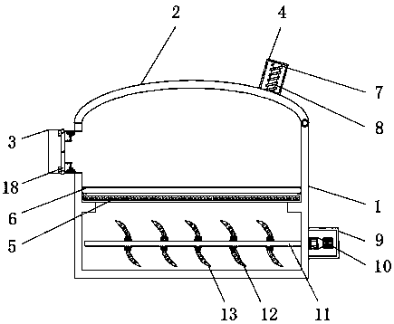
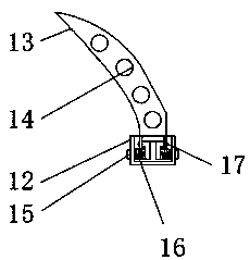
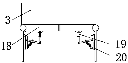
[0022] Example: refer to Figure 1-3 , the present invention provides a technical solution, a sewage treatment device that facilitates the replacement of stirring rollers, including a housing 1, a protective cover 2, a water inlet pipe 3, a protective pipe 4, a grille 5, an air gasket 6, an oxygen pipe 7, Heating wire 8, protective cover 9, motor 10, stirring shaft 11, holder 12, stirring roller 13, flow hole 14, button 15, spring 16, buckle 17, water inlet 18, reset lever 19 and return spring 20 A protective cover 2 is connected to the upper end of the housing 1, and a water inlet pipe 3 is installed on one side of the housing 1, a protective cover 9 is installed on the other side of the housing 1, and a protective tube 4 is installed on the upper end of the protective cover 2. The inside of the body 1 is provided with a grid net 5, the upper surface of the grid net 5 is equipped with an air gasket 6, the inside of the housing 1 is provided with a stirring shaft 11 close to t...


PUM


Abstract

The invention discloses a sewage treatment device with a stirring roller being replaced conveniently. The sewage treatment device comprises a shell, a protection cover is connected with the upper endof the shell, a water inlet pipe is mounted on one side of the shell, a protection shield is mounted on the other side of the shell, a protection pipe is mounted at the upper end of the protection cover, and a grid net is arranged in the shell; and a gas gasket is mounted on the upper surface of the grid net, a stirring shaft is arranged at the position, close to the lower part of the grid net, ofthe interior of the shell, and an oxygen pipe is arranged in the protection pipe. Through an electric heating wire and the protection pipe, the sewage treatment device can heat the oxygen when the oxygen passes through, thus the reaction rate of the oxygen and sewage can be improved. Through the grid net and the gas gasket, the gas gasket can lift the grid net up through the floating force when the sewage is injected, the relative speed of the grid net and the sewage is increased, and the filtration efficiency is improved. Through a fixer, the stirring roller can be conveniently replaced whenbeing damaged, and the labor intensity of workers is relieved.

Description

technical field [0001] The invention relates to the technical field of sewage treatment, in particular to a sewage treatment device which is convenient for replacing stirring rollers. Background technique [0002] Sewage treatment is the process of purifying sewage to meet the water quality requirements of a certain water body for drainage or reuse. Sewage treatment is widely used in construction, agriculture, transportation, energy, petrochemical, environmental protection, urban landscape, medical treatment, Various fields such as catering are increasingly entering the daily life of ordinary people. The traditional sewage treatment device has a complex structure and single function. The traditional sewage treatment device does not have a grille net, or the grille net is not equipped with an air gasket. , leading to low filtration efficiency of the grid mesh. The traditional sewage treatment device does not heat the oxygen when the oxygen is introduced, resulting in a slow r...

Claims


Application Information

Patent Timeline
Patent Type & Authority Applications(China)
IPC IPC(8): C02F1/72
CPCC02F1/727
Inventor 白明号
Owner 白明号
Why Eureka
Try Eureka