

Automobile accessory heat treatment device
A technology for heat treatment devices and auto parts, applied in heat treatment furnaces, heat treatment equipment, quenching devices, etc., can solve problems such as poor cooling effect and slow cooling speed, and achieve faster cooling effect, faster cooling efficiency, and faster heat transfer Effect
- Summary
- Abstract
- Description
- Claims
- Application Information
AI Technical Summary
Problems solved by technology
Method used
Image

Examples
Embodiment 1
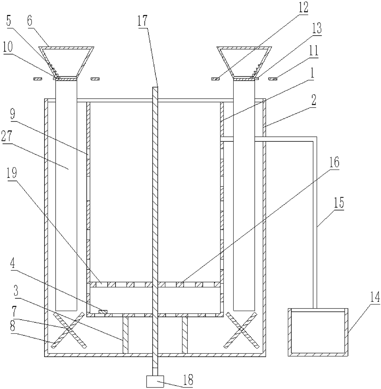
[0018] Such as figure 1 As shown, the heat treatment device for auto parts includes a frame, a first cooling box 1, a second cooling box 2, a pillar 3, a positive temperature coefficient thermistor 4, a spring 5, two drain refrigerators 6, a rotating shaft 7, and "X" type bracket 8 and the first conduit 27, the second cooling box 2 is fixed on the frame, the first cooling box 1 is located in the second cooling box 2, the first cooling box 1 has a number of first through holes 9, the first cooling box 1 A through hole 9 connects the first cooling box 1 and the second cooling box 2 , and the bottom surface of the first cooling box 1 and the bottom surface of the second cooling box 2 are fixedly connected by the pillar 3 . Two brackets 8 are respectively located on both sides of the inner wall of the second cooling box 2, and the center of the bracket 8 is fixedly connected with the rotating shaft 7, and the rotating shaft 7 is rotatably connected in the second cooling box 2; the...
Embodiment 2
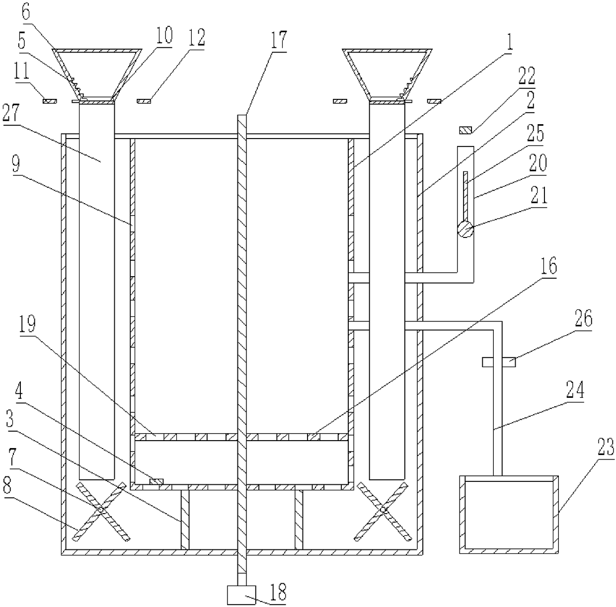
[0027] Such as figure 2 As shown, the heat treatment device for auto parts, the difference between this embodiment and the first embodiment is that the drainage unit includes a liquid level pipe 20, a float 21, a button 22 (the switch button of the model is R13-507), a second water collection tank 23, The third conduit 24 and the vertically arranged guide rod 25 have a third opening on the side wall of the middle part of the second cooling box 2, the liquid level pipe 20 communicates with the first cooling box 1, and the floating ball 21 is slidably and tightly connected to the liquid. In the position pipe 20, the floating ball 21 is connected with the guide rod 25, the button 22 is located above the conduit, the two ends of the third conduit 24 communicate with the first opening and the second water collecting tank 23 respectively, and the third conduit 24 is provided with a solenoid valve 26 , the button 22 is electrically connected to the solenoid valve 26 , and the button...
PUM
 Abstract
Description
Claims
Application Information