Spinning oiling device and control method

A spinning and suction device technology, applied in the field of spinning oiling device and control, can solve the problems of disturbing fiber forming stability, fluctuation of tow spinning process tension, failure of normal production, etc. The effect of improving the nonuniformity of breaking strength and improving the breaking strength

Active Publication Date: 2018-10-12
CHINA TEXTILE ACADEMYTIANJINSCI & TECH DEV CO LTD +1
View PDF8 Cites 4 Cited by
  • Summary
  • Abstract
  • Description
  • Claims
  • Application Information

AI Technical Summary

Problems solved by technology

However, whether it is an oil tanker or a nozzle, it is impossible to oil both sides of the fiber at the same time when oiling, and there is a time difference between the two sides of the tow or the silk, which will cause the difference in heating between the two sides of the silk condition, and the macromolecular structure inside the fiber. In addition, this kind of contact oiling will cause fluctuations in the tension of the spinning process of the tow, increasing the contact points, which will increase the fluctuations. Since the fibers are in the sensitive period of forming on the spinning process, their contact with the oiling parts There is inevitably friction, which interferes with the forming stability of the fiber. In addition, in industrialized fiber production, dozens or even thousands of filaments form a bundle, which causes some filaments to directly contact the oil when they are in contact with oil. However, some filaments can only be oiled by the penetration and infiltration of the oil agent, which inevitably leads to differences in the processes experienced by the filaments during the critical period of forming, resulting in spinning tension, Differences such as internal structure will ultimately affect the quality of fibers; especially for high-performance fibers and special-shaped fibers that require high uniformity, this difference will have a greater impact, and severe cases may cause normal production and limit high performance. fiber manufacturing

Method used


Image

  • Spinning oiling device and control method
  • Spinning oiling device and control method

Examples


Embodiment 1

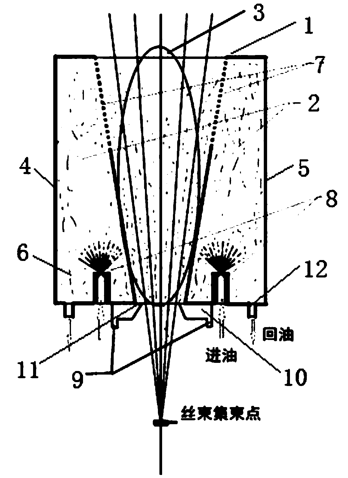
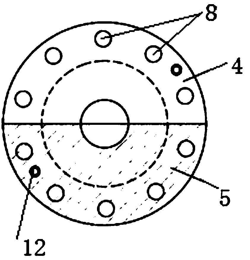
[0048] Such as figure 1 and figure 2 As shown, this embodiment provides a spinning oiling device, including a body, the body has a cavity, the cavity is filled with oil mist, when the spun fiber tow passes through the cavity, the oil in the cavity The mist oils the passing fibers.

[0049] The spinning oiling device in this embodiment is installed below the measuring blowing or surrounding blowing and above the spinning tunnel. After the spinning oil is atomized, the oil mist concentration and range can be controlled and output to the cavity, and the oiling of the tow is completed when the tow passes through this area, forming a non-contact oiling, replacing conventional oil nozzles and oil tankers Oiled spinning overcomes the problems of spinning oiling uniformity and spinning tension fluctuation in the prior art. In this way, all the fiber tows are evenly oiled through the oil mist without direct contact with the oil agent, which ensures the uniformity of oiling of indiv...

Embodiment 2

[0053] Such as figure 1 and figure 2 As shown, this embodiment is a further limitation of Embodiment 1. The spinning oiling device of this embodiment includes a body, and the body has a cavity, and the cavity is at least separated into an oil mist concentration area filled with oil mist and The fiber oiling area for the fibers to pass through, the oil mist concentration area is connected with the fiber oiling area, the oil mist in the oil mist concentration area enters the fiber oiling area, and the fibers passing through the fiber oiling area are oiled .

[0054] The cavity in this embodiment is divided into an oil mist concentration area and a fiber oiling area. The oil mist concentration area is concentrated to store the oil mist, and the fiber oiling area is for the fiber to pass through. There are many ways to separate, for example, the oil mist concentration area It is located at least on both sides of the fiber oiling area, or the oil mist concentration area can be l...

Embodiment 3

[0085] This embodiment is a further limitation of Embodiment 1. The difference between this embodiment and Embodiment 2 is that the first oiling part and the second oiling part of this embodiment are integrated and cannot be moved relative to each other, and they form a ring together inside. The hollow chamber, the radial cross-sectional area of ​​the annular hollow chamber gradually increases from bottom to top. The hollow part in the center of the annular hollow chamber forms a fiber oiling area, and when the fiber passes, the oil mist oils the fiber.


PUM


Abstract

The invention belongs to the field of spinning and discloses a spinning oiling device and a control method. The spinning oiling device comprises a body, the body is provided with a cavity, and the cavity is filled with oil mist. When fibers for spinning pass through the cavity, the oil mist in the cavity oils the passing fibers. The cavity is divided into an oil mist concentration zone filled withthe oil mist and a fiber oiling zone through which the fibers pass, the oil mist concentration zone is communicated with the fiber oiling zone, and the oil mist in the oil mist concentration zone enters the fiber oiling zone to oil the fibers passing through the fiber oiling zone. A novel spinning oiling concept is provided; through a non-contact oil mist oiling mode, the difference of the oilingquantity of a single fiber in a bundle of fibers within oiling time can be effectively reduced, the spinning process tension in a spinning process is improved, and the quality of the fibers is improved.

Description

technical field [0001] The invention relates to the field of spinning and manufacturing, and relates to a spinning oiling device and a control method. Background technique [0002] In the melt spinning process, the fiber-forming polymer is melted to form a spinning melt, which is then metered by a metering pump, and then refined through the densely distributed spinneret holes of the spinneret of the spinning assembly to form chemical fibers. [0003] The production process of chemical fiber is as follows. The fiber-forming high polymer is melted to form a uniform spinning melt, and then quantitatively metered by a metering pump, it is input to the spinning assembly, filtered and distributed in the spinning assembly, and then from the spinning The small holes of the plate flow out to form a fine fiber stream, which is stretched, thinned and solidified to form a fiber, and the fiber tow is formed into a fiber product after oiling, drafting, winding and other processes. [000...

Claims


Application Information

Patent Timeline
Patent Type & Authority Applications(China)
IPC IPC(8): D01D5/096D01D13/02
CPCD01D5/096D01D13/02
Inventor 吴鹏飞崔华帅史贤宁崔宁李杰黄庆
Owner CHINA TEXTILE ACADEMYTIANJINSCI & TECH DEV CO LTD
Why Eureka
Try Eureka