Prefabricated supporting structure and construction method using the supporting structure

A technology of support structure and construction method, which is applied to temporary shields, shaft equipment, earthwork drilling and mining, etc., can solve the problems of low construction efficiency, high labor construction intensity, and slow construction speed, so as to improve construction efficiency and ensure construction Safety, fast construction effect

Active Publication Date: 2020-08-25
SHANDONG UNIV +1
View PDF6 Cites 1 Cited by
  • Summary
  • Abstract
  • Description
  • Claims
  • Application Information

AI Technical Summary

Problems solved by technology

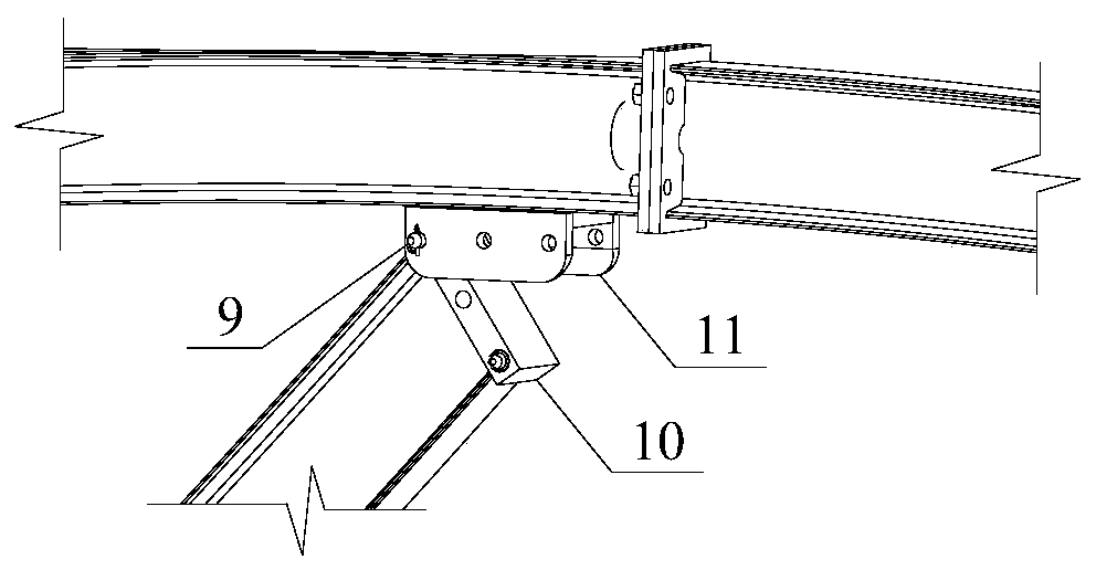
[0004] 1. The joints of the temporary support and support structure adopt the existing ordinary flange joints, and the single-section arch frame is spliced ​​manually. This joint structure leads to problems such as slow construction speed and low construction efficiency;
[0005] 2. At present, there is no prefabricated arch frame in the underground engineering. After the tunnel excavation is completed, without any support measures, the manual installation of the arch frame is the most dangerous construction link in the tunnel construction process; during this period , high-intensity, high-load construction, workers are easily fatigued, and the stability of the surrounding rock is poor, and its construction safety must be strictly guaranteed during tunnel construction
In addition, with the disappearance of the demographic dividend, the contradiction between human resource costs and engineering economy has become increasingly prominent
[0006] 3. During the excavation and support process of the tunnel subdivision method, the arch support structure needs to be erected in sections, which is difficult to construct, and the flange nodes of each section of the arch frame are connected by manually installing flange nodes; the arch frame is heavy and the labor construction intensity Large, low construction efficiency, slow progress of traditional construction methods

Method used


Image

  • Prefabricated supporting structure and construction method using the supporting structure
  • Prefabricated supporting structure and construction method using the supporting structure
  • Prefabricated supporting structure and construction method using the supporting structure

Examples


Embodiment Construction

[0045] specific implementation plan

[0046] It should be pointed out that the following detailed description is exemplary and intended to provide further explanation to the present application. Unless defined otherwise, all technical and scientific terms used herein have the same meaning as commonly understood by one of ordinary skill in the art to which this application belongs.

[0047]It should be noted that the terminology used here is only for describing specific implementations, and is not intended to limit the exemplary implementations according to the present application. As used herein, unless the context clearly dictates otherwise, the singular is intended to include the plural, and it should also be understood that when the terms "comprising" and / or "comprising" are used in this specification, they mean There are features, steps, operations, devices, components and / or combinations thereof; for the convenience of description, if the words "upper", "lower", "left" a...


PUM


Abstract

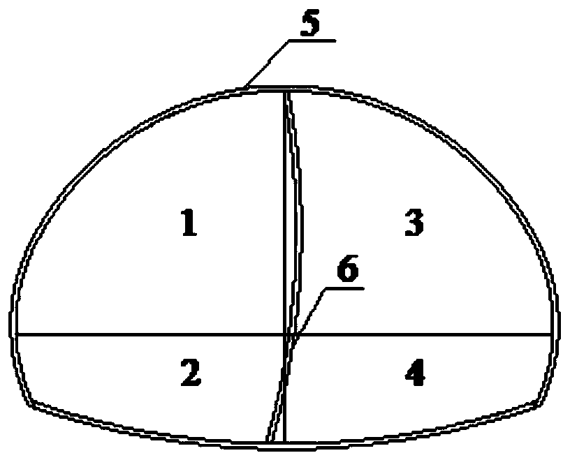
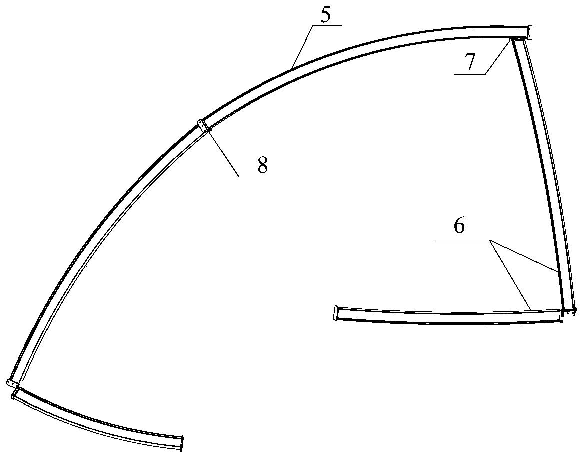
The invention discloses a tunnel sectional excavation assembly arch frame and mechanized construction technology. An excavation process of a tunnel CD method is taken as an example, the arch frame isfolded according to sectional sections, and an arch frame assembling machine lifts the arch frame to the front of a tunnel face; the arch frame of a first excavation part and temporary support are connected and fixed, and the arch frame is grabbed and lifted by the arch frame assembling machine, and the arch frame and the temporary support are fully spread and positioned; an inverted-arch arch frame of a second excavation part on the lower portion of the left side and the temporary support of the remaining part are installed and are connect with the arch frame of a first excavation part on theupper portion of the left side and temporary support; a supporting arch frame of a third excavation part on the upper portion of the right side is installed and is connected with the arch frame of the first excavation part on the upper portion of the left side; and an inverted-arch of a excavation part on the lower portion of the right side is installed and is connected with and the supporting arch frame of the third excavation part on the upper portion of the right side and the inverted-arch of the second excavation part on the lower portion of the left side. The mechanized installation of asectional support structure is achieved, the construction efficiency is improved, and the construction safety is ensured.

Description

technical field [0001] The invention is applicable to a subdivisional excavation process of an underground project, and in particular relates to a flange node, an assembled support structure including the node, and a construction technique for mechanized rapid construction using an assembled arch frame. Background technique [0002] With the rapid development of traffic tunnel construction, the construction scale is gradually increasing. During the construction process, it is inevitable to encounter complex geological conditions such as weak surrounding rocks and fault fracture zones. The surrounding rocks are loose and damaged, and the vaults are often unstable. The stress concentration and other characteristics of the arch foot lead to safety problems such as large deformation of the surrounding rock, broken supporting components, broken blocks of the vault and even landslides, which may easily cause casualties and major economic losses. [0003] At present, there are the ...

Claims


Application Information

Patent Timeline
Patent Type & Authority Patents(China)
IPC IPC(8): E21D9/00E21D11/18E21D19/00
CPCE21D9/00E21D11/18E21D19/00
Inventor 王琦江贝栾英成
Owner SHANDONG UNIV
Why Eureka
Try Eureka