Hydraulically-driven mud pump

A mud pump and hydraulic technology, applied in the field of mud pumps, can solve the problems of unsuitable use, short service life, unreliability, etc., and achieve the effect of simple structure, long stroke and reduced stroke times

Active Publication Date: 2018-10-12
阿奥艾斯海洋工程(上海)有限公司
View PDF7 Cites 1 Cited by
  • Summary
  • Abstract
  • Description
  • Claims
  • Application Information

AI Technical Summary

Problems solved by technology

The three comparative patents retrieved above indicate that hydraulically driven single-cylinder double-acting forms are not used in the field of mud pumps, and their common feature is that although they are all hydraulically controlled double-acting pumps, they The commutation problem is realized by the micro switch of the mechanical movement collision circuit. In practical application, there must be electronic control, which is not suitable for use in the explosion-proof environment; and because the micro switch has been bumped many times, the service life is short short, unreliable
In addition, the existing hydraulically driven mud pumps on the market will generate noise due to the collision between the piston and the cylinder head after the drive cylinder moves to the end in one direction.

Method used


Image

  • Hydraulically-driven mud pump
  • Hydraulically-driven mud pump
  • Hydraulically-driven mud pump

Examples


Embodiment Construction

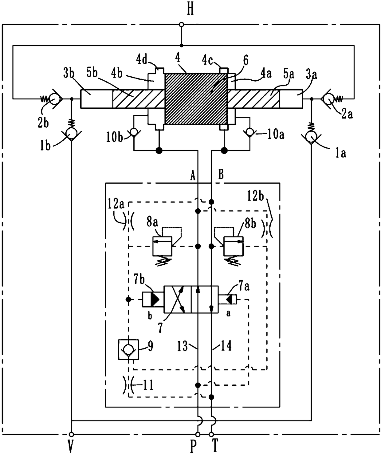
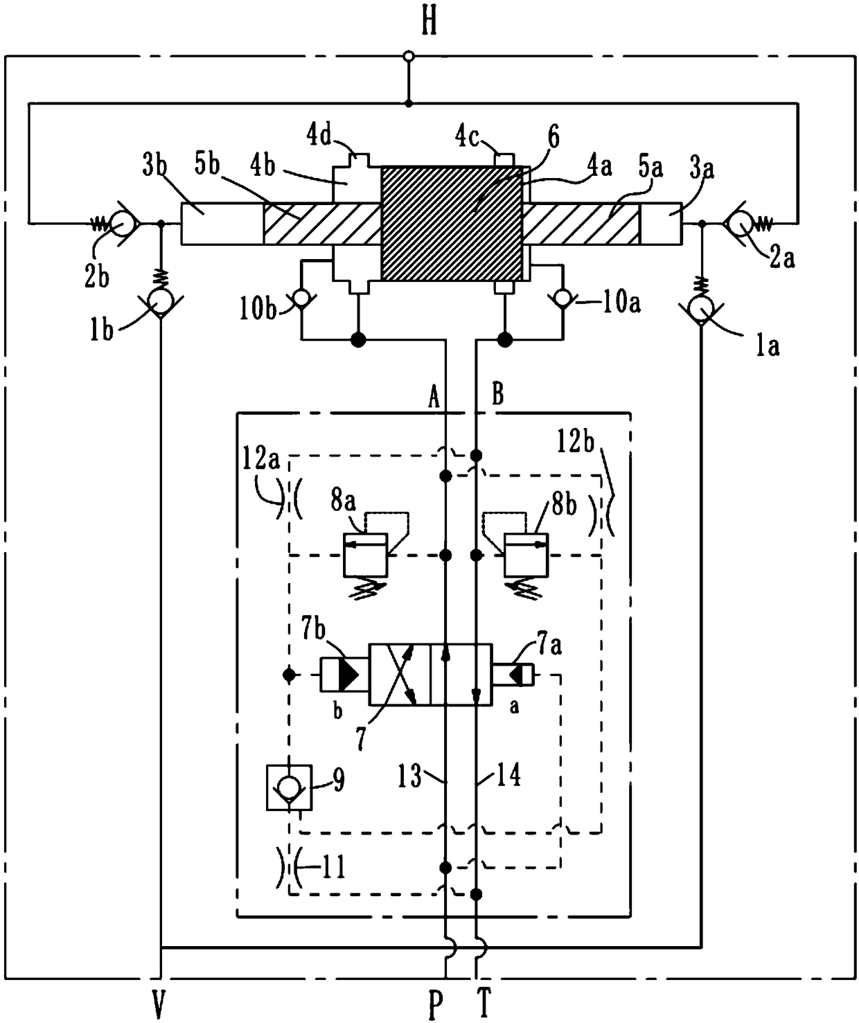
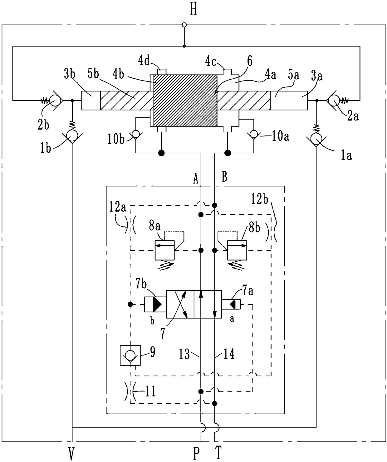
[0021] see Figure 1-3, as a preferred embodiment of the present invention, the present invention provides a hydraulically driven mud pump, which is provided with an oil inlet P, an oil return port T, a slurry inlet V, and a high-pressure slurry outlet H, which includes a booster cylinder and Hydraulic control reversing valve assembly; booster cylinder includes low-pressure cylinder 4, low-pressure piston 6, left high-pressure plunger 5b, right high-pressure plunger 5a, left high-pressure cylinder 3b and right high-pressure cylinder 3a, and low-pressure piston 6 is slidably set on low-pressure cylinder 4 There are left piston cavity 4b and right piston cavity 4a respectively formed at its left and right ends, and its left and right ends are respectively connected with the left high pressure plunger 5b and the right high pressure column in the right high pressure cylinder 3b which are slidably arranged in the left high pressure cylinder 3b. The plug 5a is connected, and the lef...


PUM


Abstract

The invention discloses a hydraulically-driven mud pump. The hydraulically-driven mud pump is provided with an oil inlet port P, an oil return port T, a mud inlet port V and a high-pressure mud outletport H. The hydraulically-driven mud pump comprises a pressurization cylinder and a hydraulically-controlled reversing valve assembly, wherein the pressurization cylinder comprises a low-pressure cylinder, a low-pressure piston, a left high-pressure plunger, a right high-pressure plunger, a left high-pressure cylinder and a right high-pressure cylinder, and a first through-flow groove and a second through-flow groove are formed in the low-pressure cylinder; when the low-pressure piston moves to the left and reaches to a position that the low-pressure piston completely shields the first through-flow groove, the low-pressure piston brakes through an airtight left piston cavity, and triggers the hydraulically-controlled reversing valve assembly to act to reverse; and when the low-pressure piston moves to the right and reaches to a position that the low-pressure piston completely shields the second through-flow groove, the low-pressure piston brakes through an airtight right piston cavity, and triggers the hydraulically-controlled reversing valve assembly to act to reverse. The hydraulically-driven mud pump is simple in structure, does not need to be controlled through electronic control, and is low in noise.

Description

technical field [0001] The invention relates to the technical field of mud pumps, in particular to a hydraulically driven mud pump. Background technique [0002] In the field of engineering, especially in the petroleum industry, it is necessary to transport liquids with high viscosity, large specific gravity or high sand content and relatively low flow rate under high pressure, such as circulating mud and injecting cement when sticking wells, and used for oil production Crude oil transportation, well washing and water injection and formation fracturing, so the mud pump is a common key equipment in the petroleum industry. At present, most of the mud pumps at home and abroad adopt the form of mechanical drive. From the perspective of obtaining the reciprocating motion of the pump, the single-cylinder single-acting pump driven by the crank slider has no practical significance, because its displacement is very uneven. , whose value is 3.14; in addition, there are three-cylinder...

Claims


Application Information

Patent Timeline
Patent Type & Authority Applications(China)
IPC IPC(8): F04B9/113F04B15/02F04B49/00
CPCF04B9/113F04B15/02F04B49/002
Inventor 邵玉刚
Owner 阿奥艾斯海洋工程(上海)有限公司
Why Eureka
Try Eureka