Full wave-transparent zone plate

A wave-transmitting, strip-plate technology, applied in the field of optical components, can solve the problems of low light intensity of the focused spot and low utilization rate of the light source, etc., and achieve the effect of reducing the full width at half maximum

Active Publication Date: 2018-10-12
SHENZHEN UNIV
View PDF8 Cites 2 Cited by
  • Summary
  • Abstract
  • Description
  • Claims
  • Application Information

AI Technical Summary

Problems solved by technology

However, since the Fresnel zone plate only allows half of the incident waves to undergo diffraction coherent superposition, while the other half of the incident waves are shielded, the utilization of the light source is not high, and the focused spot light intensity is low

Method used


Image

  • Full wave-transparent zone plate
  • Full wave-transparent zone plate
  • Full wave-transparent zone plate

Examples


Embodiment Construction

[0023] The following will clearly and completely describe the technical solutions in the embodiments of the present application with reference to the drawings in the embodiments of the present application. Obviously, the described embodiments are part of the embodiments of the present application, not all of them. Based on the embodiments in this application, all other embodiments obtained by persons of ordinary skill in the art without making creative efforts belong to the scope of protection of this application.

[0024] exist Figure 1 to Figure 5 In , the same or similar structures are denoted by the same reference numerals.

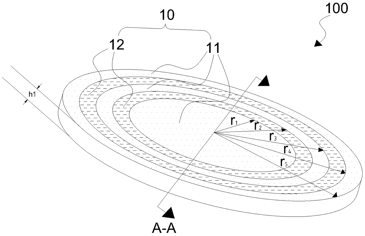
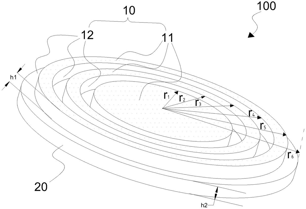
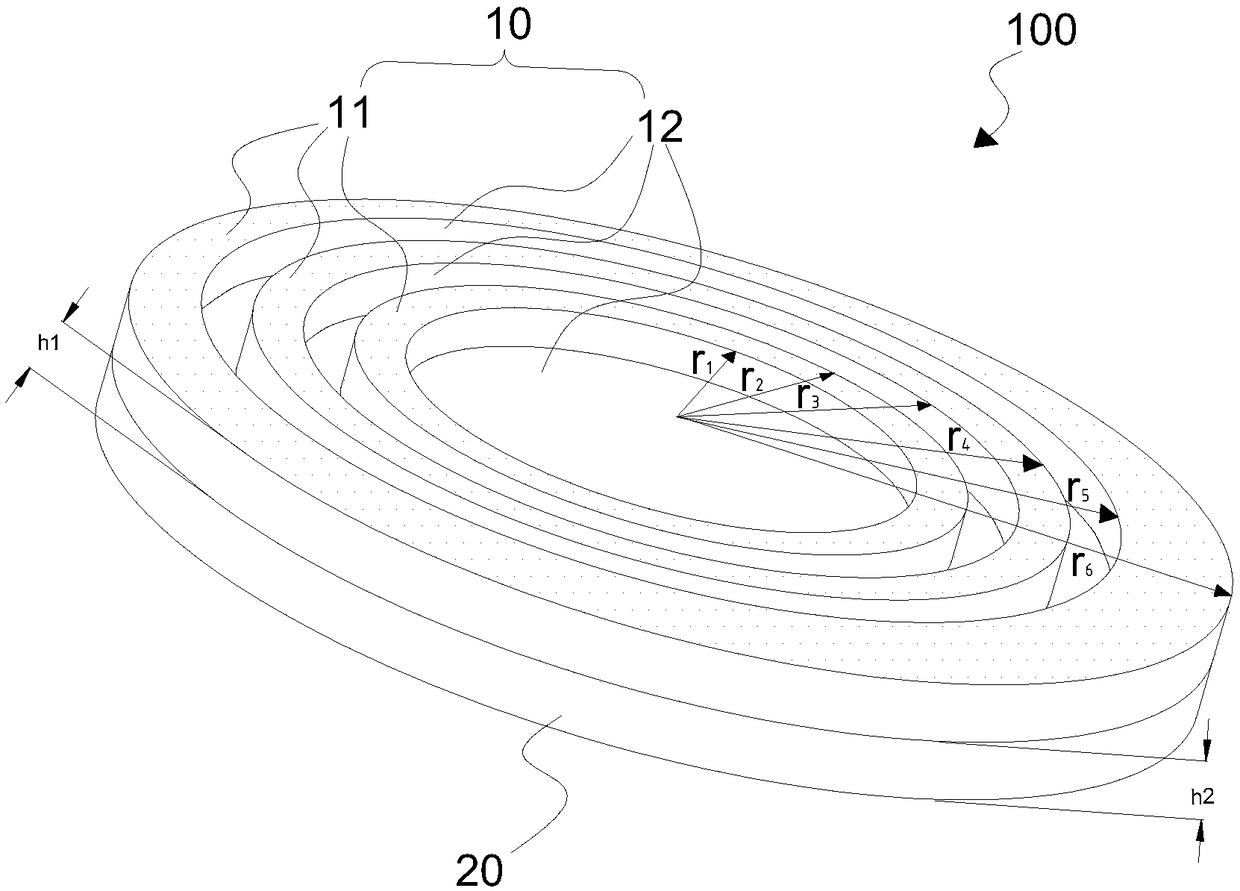
[0025] see figure 1 , figure 1 It is a structural schematic diagram of a fully transparent zone plate provided in the embodiment of this application. The fully transparent zone plate 100 can be used to focus terahertz waves or millimeter waves. The fully transparent zone plate 100 includes concentric ring structures 10 . The concentric ring stru...


PUM


Abstract

The embodiment of the invention discloses a full wave-transparent zone plate. The full wave-transparent zone plate includes a concentric ring structure, wherein the concentric ring structure includesa first ring body and a second ring body which are alternately arranged, and the radius rk of the kth ring of the concentric ring structure satisfies the formula (as shown in the description), whereinf is the focal length of the full wave-transparent zone plate, and lambda is the wavelength of the incoming wave, and k is a positive integer; and the first ring body and the second ring body have the same height and satisfy the formula (as shown in the description), wherein n1 is the refractive index of the second ring body, and a is a positive odd number. The full wave-transparent zone plate can focus the parallel incoming wave, and can improve the light intensity of the focused light spot and the focusing efficiency.

Description

technical field [0001] The present application relates to the technical field of optical components, in particular to a fully transparent zone plate. Background technique [0002] In terahertz, millimeter wave and other wave bands, the problem of focusing is often involved. The traditional focusing method is to use lenses and parabolic mirrors for focusing, but lenses and parabolic mirrors tend to produce large spherical aberrations during the focusing process, and due to the large size of lenses and parabolic mirrors, in some compact and precise instruments or The lens and parabolic mirror cannot be used in the optical path for focusing. In order to reduce spherical aberration and reduce the volume of focusing components, Fresnel zone plates can also be used for focusing. The Fresnel zone plate uses the principle of diffraction coherent superposition to focus the incident terahertz waves, millimeter waves, etc. However, since the Fresnel zone plate only allows half of th...

Claims


Application Information

Patent Timeline
Patent Type & Authority Applications(China)
IPC IPC(8): G02B5/18
CPCG02B5/1876
Inventor 梁华伟尹慧张敏苏红李玲
Owner SHENZHEN UNIV
Why Eureka
Try Eureka