A self-phase-shifted dual-frequency dual-circularly polarized cross-dipole antenna

A dual circularly polarized, cross-dipole technology, which is applied in the connection of antennas, antenna grounding switch structures, and devices that make antennas work in different frequency bands at the same time, can solve complex processing technology, difficult antenna integration, and difficulty in implementing power division networks. Multiple frequency band phase control and other issues to achieve a good matching effect

Active Publication Date: 2021-04-06
FOSHAN SHUNDE SUN YAT SEN UNIV RES INST +2
View PDF7 Cites 0 Cited by
  • Summary
  • Abstract
  • Description
  • Claims
  • Application Information

AI Technical Summary

Problems solved by technology

[0003] Usually, the circularly polarized antenna that achieves phase control through the power-dividing feed network can achieve good circular polarization performance at a single frequency point, but due to the existence of the complex feed network, the processing technology is complicated and the antenna is difficult to It is integrated into the communication system, so it is difficult to apply to portable devices, and the power division network is difficult to achieve phase control of multiple frequency bands, and the antenna cannot achieve circular polarization characteristics in multiple frequency bands

Method used


Image

  • A self-phase-shifted dual-frequency dual-circularly polarized cross-dipole antenna
  • A self-phase-shifted dual-frequency dual-circularly polarized cross-dipole antenna
  • A self-phase-shifted dual-frequency dual-circularly polarized cross-dipole antenna

Examples


Embodiment 1

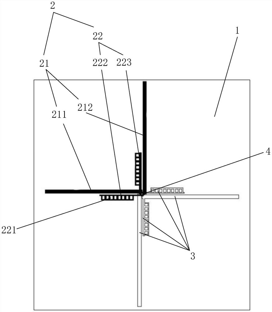
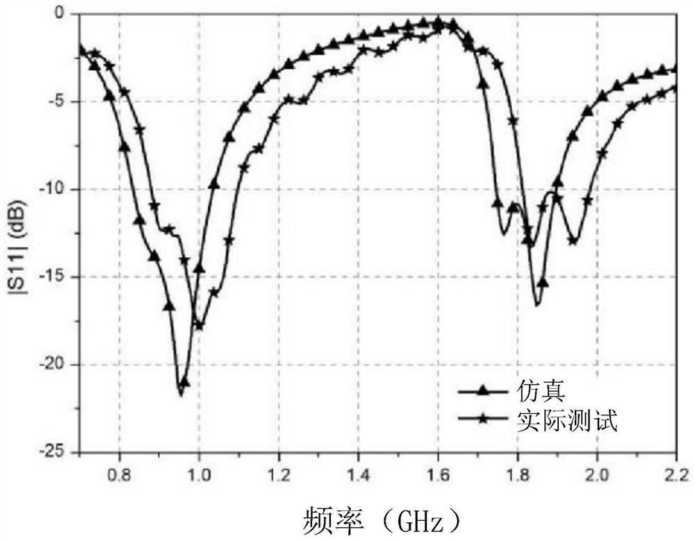
[0030] Embodiment 1 is to adopt the mode of elongated branches, with reference to figure 1 As shown, the dielectric board 1 used in Example 1 is a FR-4 epoxy glass fiber cloth dielectric board with a thickness of 2mm, a dielectric constant of 4.7, a loss tangent of 0.01, and a size of 150mm*150mm. The first branch The length of 211 is 65mm, the length of the second branch 212 is 56mm, the widths of the first branch 211 and the second branch 212 are 2mm, the length and width of the third branch 222 are 24mm and 1mm respectively, and the fourth branch 223 The length and width of the antenna are 25mm and 0.5mm respectively. In the present embodiment, the frequency covered by the low frequency part of the antenna work is from 830MHz to 1GHz, and the working bandwidth is 170MHz, covering GSM900, China Telecom CDMA and other mobile communication frequency bands; the high frequency part The frequency covered is from 1.74GHz to 1.89MHz, and the working bandwidth is 150MHz, covering DC...

Embodiment 2

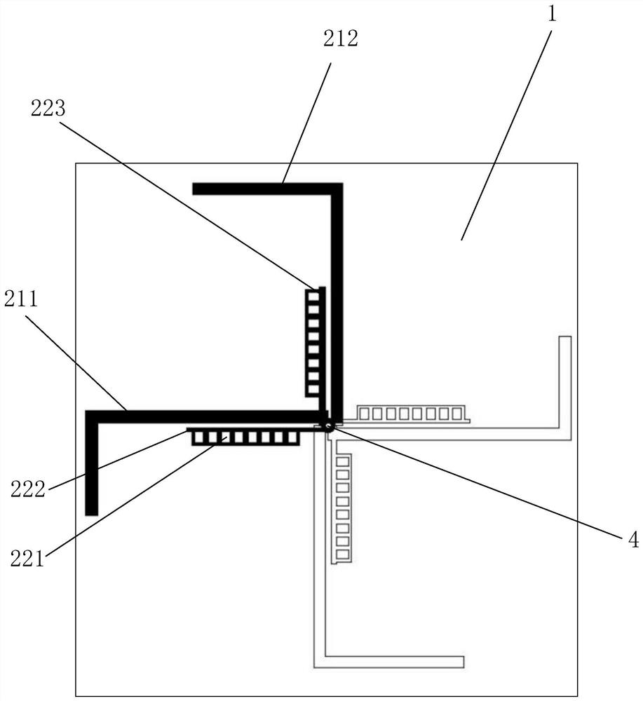
[0032] Embodiment 2 is to adopt the mode that branch is carried out 90 degree bending, refer to image 3 As shown, the first branch 211 and the second branch 212 are bent and folded at 90 degrees, and the length of each branch is adjusted at the same time to generate a length difference to obtain the required operating frequency and circular polarization characteristics. In this embodiment, the The dielectric board 1 is an FR-4 epoxy glass fiber cloth dielectric board with a thickness of 2mm, a dielectric constant of 4.7, and a loss tangent of 0.01. The size of the dielectric board 1 is 100mm*100mm, and the first branch 211 The length is 68mm, the length of the second branch 212 is 58mm, the width of the first branch 211 and the second branch 212 is 2mm, the length and width of the third branch 222 are respectively 24mm and 0.8mm, the fourth branch 223 The length and width are 24.5mm and 1mm respectively, and the antenna of embodiment 2 is also simulated and actually tested, r...

Embodiment 3

[0034] Embodiment 3 adopts the mode of serpentine bending, referring to Figure 5 As shown, in order to further miniaturize the antenna, the first branch 211 and the second branch 212 are bent in a serpentine shape, and the third branch 222 and the fourth branch 223 are bent at 90 degrees, which can greatly improve the To reduce the size of the antenna, in this embodiment, the size of the dielectric plate 1 is only 75mm*75mm, the thickness is 2mm, the dielectric constant is 4.7, and the loss tangent is 0.01.

[0035] However, due to the large coupling at the serpentine bend, the resistance of the antenna at low frequencies is small, and the impedance bandwidth is small. Therefore, in order to expand the impedance bandwidth at low frequencies, the first dipole arm 2 and the second dipole arm A 200Ω resistor is added to each branch of 3, and the corresponding impedance bandwidth is obtained by sacrificing the gain. Due to the addition of the resistor, a sufficiently high resista...


PUM


Abstract

The invention discloses a self-phase-shifted dual-frequency dual-circularly polarized cross-dipole antenna, which includes a dielectric plate, a first dipole arm and a second dipole arm, and the first dipole arm and the second dipole The sub-arms are respectively arranged on both sides of the dielectric plate. The first dipole arm and the second dipole arm respectively include a low-frequency radiation stub group and a high-frequency radiation stub group. By adjusting the low-frequency radiation stub group and the high-frequency radiation stub group The length of the stub can make the antenna have circular polarization characteristics at both low frequency and high frequency, and a grid is arranged on the high frequency radiation stub group, so that the antenna can obtain a better matching effect at high frequency. The present invention The complex power distribution and feeding network is omitted, and the structure of the antenna is relatively simple, which enables the antenna to achieve dual-frequency operation, and has circular polarization characteristics in both operating frequency bands.

Description

technical field [0001] The invention relates to the technical field of antenna communication, in particular to a self-phase-shifted dual-frequency dual circularly polarized crossed dipole antenna. Background technique [0002] As the eyes of the wireless communication system, the antenna directly affects the quality of the communication. In the antenna design, the half-wave dipole antenna is widely used in the communication system because of its simple structure, good performance and low manufacturing cost, while the circularly polarized antenna can Receiving signals transmitted in any direction has obvious advantages in anti-multipath interference, suppression of rain and fog interference, and improvement of channel capacity. Designing circularly polarized antennas with low axial ratio, multi-frequency, and broadband characteristics is the key to future mass data transmission. key technologies. [0003] Usually, the circularly polarized antenna that achieves phase control ...

Claims


Application Information

Patent Timeline
Patent Type & Authority Patents(China)
IPC IPC(8): H01Q5/10H01Q5/307H01Q5/50H01Q1/36H01Q1/50
CPCH01Q1/36H01Q1/50H01Q5/10H01Q5/307H01Q5/50
Inventor 谭洪舟陈智聪曾淼旺黎梓宏苗登喜廖肇荣路崇
Owner FOSHAN SHUNDE SUN YAT SEN UNIV RES INST
Why Eureka
Try Eureka