Battery pack equalizing circuit and equalizing method

A technology of equalization circuit and equalizer circuit, applied in charge equalization circuit, battery circuit device, charging/discharging of secondary battery, etc., can solve the problems of low equalization energy transfer efficiency and low equalization speed, etc.

Pending Publication Date: 2018-10-12
安徽汉星储能技术有限公司
View PDF0 Cites 2 Cited by
  • Summary
  • Abstract
  • Description
  • Claims
  • Application Information

AI Technical Summary

Problems solved by technology

[0005] The technical problem to be solved by the present invention is to provide a battery pack equalization circuit and equalization method to solve the problems of low equalizat

Method used


Image

  • Battery pack equalizing circuit and equalizing method
  • Battery pack equalizing circuit and equalizing method
  • Battery pack equalizing circuit and equalizing method

Examples


Embodiment 1

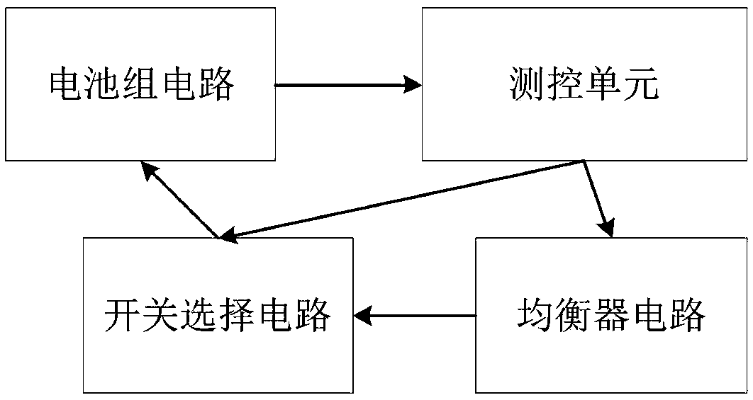
[0040] A battery pack balancing circuit, such as the attached figure 1 As shown, it includes a battery pack circuit, a switch selection circuit, an equalizer circuit and a measurement and control unit. The measurement and control unit is connected to the equalizer circuit and the switch selection circuit, and the switch selection circuit is also connected to the battery pack circuit and the equalizer circuit respectively.

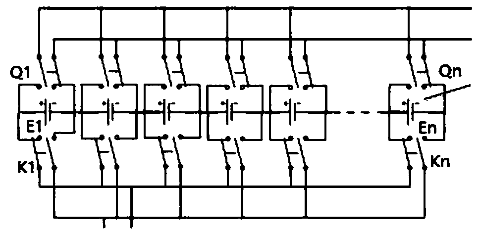
[0041] Wherein, the battery pack circuit includes n single cells E1-En, where n>1, and n=10 is taken as an example for illustration in the embodiment of the present invention.

[0042] attached figure 2 Shown is the schematic diagram of the structure of the switch selection circuit, as attached figure 2 As shown, the switch selection circuit includes a first selection module and a second selection module.

[0043] The first selection module includes 10 dual-channel relays Q1-Q10, the dual-channel relay Qi is connected to the single battery Ei, the first...

Embodiment 2

[0058] A battery pack balancing method, the method comprising the following steps:

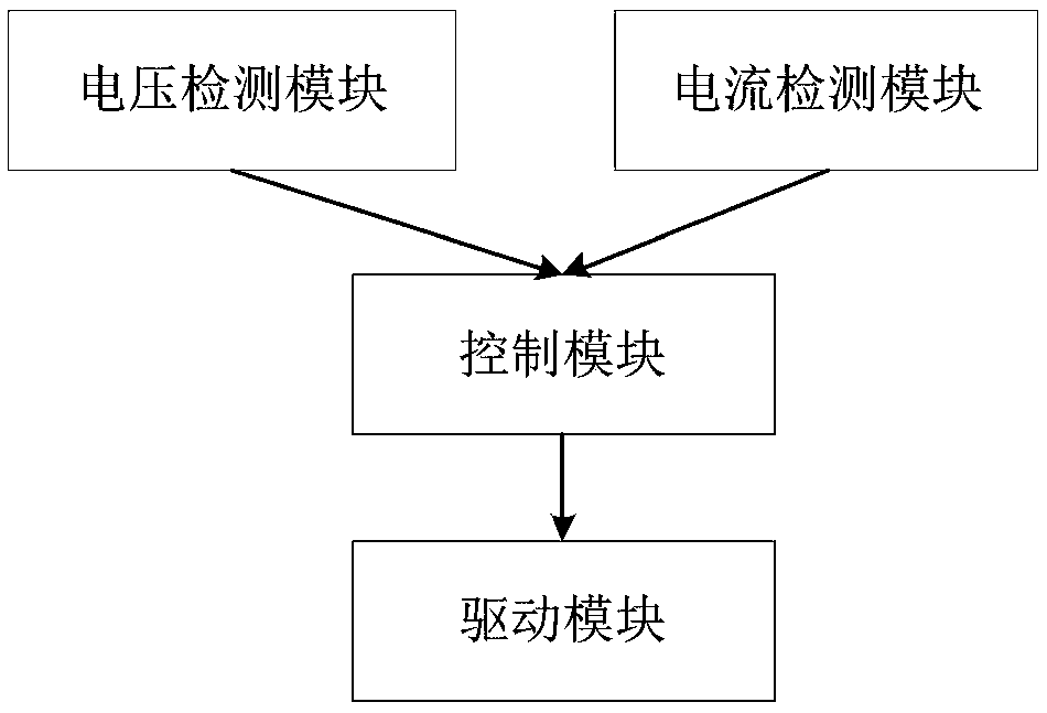
[0059] Step S1, setting equalization conditions, said equalization conditions include the SOC threshold or voltage threshold of the battery cell, in the prior art, the voltage threshold is generally set, but since the embodiment of the present invention is provided with a voltage acquisition module and a current acquisition module , SOC is calculated according to the current and voltage values, so the embodiments of the present invention can use the SOC threshold or voltage threshold as the equilibrium condition;

[0060] Step S2. Collect the current and voltage of each battery cell, and calculate the SOC of the battery cell. If the balance condition is the voltage threshold, then it is enough to collect the voltage of the battery cell. If the balance condition is the SOC threshold, it is necessary to collect The current and voltage of each battery cell, and calculate the SOC of the battery ce...


PUM


Abstract

The invention discloses a battery pack equalizing circuit and an equalizing method. The battery pack equalizing circuit comprises a battery pack circuit, a switch selection circuit, an equalizer circuit and a measure and control unit; the battery pack circuit comprises n unit cells; the switch selection circuit is connected with the circuit pack circuit; the measure and control unit comprises a control module, a driving module, a voltage detection module and a current detection module; the voltage detection module is connected with each unit cell, and is used for detecting the voltage of eachunit cell; the current detection module is connected with the equalizer circuit, and is used for detecting the equalizing current; the control module is respectively connected with the equalizer circuit, the driving module, the voltage detection module and the current detection module; the driving module is connected with the switch selection circuit, and is used for equalizing the voltage of thebattery pack according to the control of the control module; and the equalizer circuit is further connected with the switch selection circuit, and is used for equalizing the current of the battery pack according to the control of the control module. The battery pack equalizing circuit and the equalizing method disclosed by the invention can adopt various equalization strategies to achieve charge and discharge equalization of the battery pack.

Description

technical field [0001] The invention relates to the field of electronic circuits, in particular to a battery pack equalization circuit and an equalization method. Background technique [0002] In the industrialization project of the new energy system, the performance of the battery is one of the key factors affecting the performance of the entire system, and at the same time occupies a relatively high proportion of the cost. It can even be said that the battery plays a decisive role in the entire new energy industry. However, the physical differences of the single battery during the manufacturing process and the different internal and external environments in the use process lead to the gradual deterioration of the consistency of the single battery. According to the "short plate effect principle", the capacity utilization rate and cycle life of the battery pack are seriously lower than that of the single battery. Therefore, it is necessary to apply a battery balancing circu...

Claims


Application Information

Patent Timeline
IPC IPC(8): H02J7/00H01M10/44G01R31/36
CPCH01M10/441H02J7/0019Y02E60/10
Inventor 武银行
Owner 安徽汉星储能技术有限公司
Why Eureka
Try Eureka