Unified mode control method for non-inverting Buck-Boost converter

A mode control and converter technology, applied in control/regulation systems, conversion of DC power input to DC power output, instruments, etc., can solve problems such as poor dynamic performance

Inactive Publication Date: 2018-10-12
SHANGHAI JIAO TONG UNIV
View PDF1 Cites 3 Cited by
  • Summary
  • Abstract
  • Description
  • Claims
  • Application Information

AI Technical Summary

Problems solved by technology

This mode switching strategy requires an additional voltage sensor to measure the input voltage
In addition, the dynamic

Method used


Image

  • Unified mode control method for non-inverting Buck-Boost converter
  • Unified mode control method for non-inverting Buck-Boost converter
  • Unified mode control method for non-inverting Buck-Boost converter

Examples


Embodiment 1

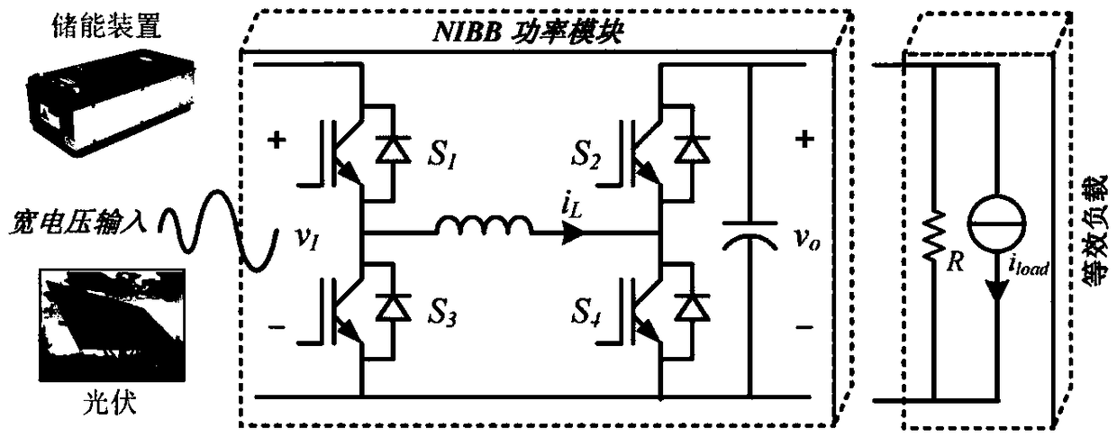
[0147] For example figure 1 The shown NIBB circuit diagram is simulated, and the parameters of each component of the circuit are: C=1mF, L=1mH, R=20Ω. According to the circuit parameters, take V in = 48V. The unified mode controller designed based on LMI is [-0.93,-2.9,-587].

[0148] In order to verify the effectiveness of the unified mode controller, the design and Figure 6 Equivalent discrete-mode controllers such as Figure 8 shown. The inner loop uses proportional control and the outer loop uses PI control. The control parameter is set to: k vp =3,k vi =540,k ip = 0.16.

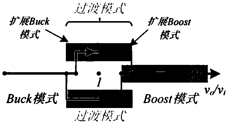
[0149] The performance of unified mode control and discrete mode control is compared under load ramping and load ramping conditions. During simulation, use numbers to represent each working mode of NIBB, among which 1 represents Buck mode, 2 represents extended Buck mode, 3 represents extended Boost mode, and 4 represents Boost mode.

[0150] 1) Response when the load increases

[0151] The ...


PUM


Abstract

The invention provides a unified mode control method for a non-inverting Buck-Boost converter (NIBB). By establishing an average model and a unified mode control model of the NIBB, under the control of the unified mode, the input control amount is the equivalent duty ratio d, and the duty ratio is finally calculated by the Buck mode, the extended Buck mode, the extended Boost mode and the Boost mode. The working mode of the controller provided by the invention is completely determined by the equivalent duty ratio, and no additional input voltage sensor is needed compared with the discrete modecontrol, thereby reducing the system cost. The invention realizes flexible switching of each working mode of the converter under transient state, reduces the output settling time and recovery time ofthe controller, reduces the output voltage deviation, and improves the system dynamic performance, thereby reducing the number of active switches per cycle, reducing overall switching dynamic loss, and improving conversion effectiveness of a DC-DC converter compared with synchronous control.

Description

technical field [0001] The present application relates to the fields of new energy power generation and control of power electronic converters, in particular to a unified mode control method for non-inverting Buck-Boost converters, which is used for operation control of multi-mode DC-DC converter circuits. Background technique [0002] In DC distribution network and DC micro-grid, the DC output of renewable energy and energy storage equipment has the characteristics of wide voltage, and its output voltage fluctuates in a wide range with the change of specific working conditions. When renewable energy and energy storage equipment are converted and connected to the grid through a DC-DC converter, there is often an overlap between the input voltage range and the output voltage range of the DC-DC converter. This requires that the DC-DC converter not only has the ability to step up, but also has the ability to step down. Non-inverting Buck-Boost converter (Non-inverting Buck-Boo...

Claims


Application Information

Patent Timeline
IPC IPC(8): H02M3/156
CPCH02M3/156
Inventor 朱淼徐莉婷马建军蔡旭
Owner SHANGHAI JIAO TONG UNIV
Why Eureka
Try Eureka