Building template automatic drilling machine and operating method

A construction template, drilling machine technology, applied in the direction of boring/drilling, drilling/drilling equipment, metal processing machinery parts, etc., can solve the problem of low work efficiency, high labor intensity of operators, and poor drilling quality. Good guarantee and other issues to achieve the effect of reducing labor intensity, improving drilling efficiency and drilling quality

Inactive Publication Date: 2018-10-16
湖北绿筑装配科技有限公司
View PDF18 Cites 4 Cited by
  • Summary
  • Abstract
  • Description
  • Claims
  • Application Information

AI Technical Summary

Problems solved by technology

[0003] (1) Due to the large number of holes, manual drilling is used, and the work efficiency is low;
[0004] (2) The labor intensity of the operators is high, which is not conducive to long-term operations;
[0005] (3) The drilling quality is not well guaranteed

Method used


Image

  • Building template automatic drilling machine and operating method
  • Building template automatic drilling machine and operating method
  • Building template automatic drilling machine and operating method

Examples


Embodiment 1

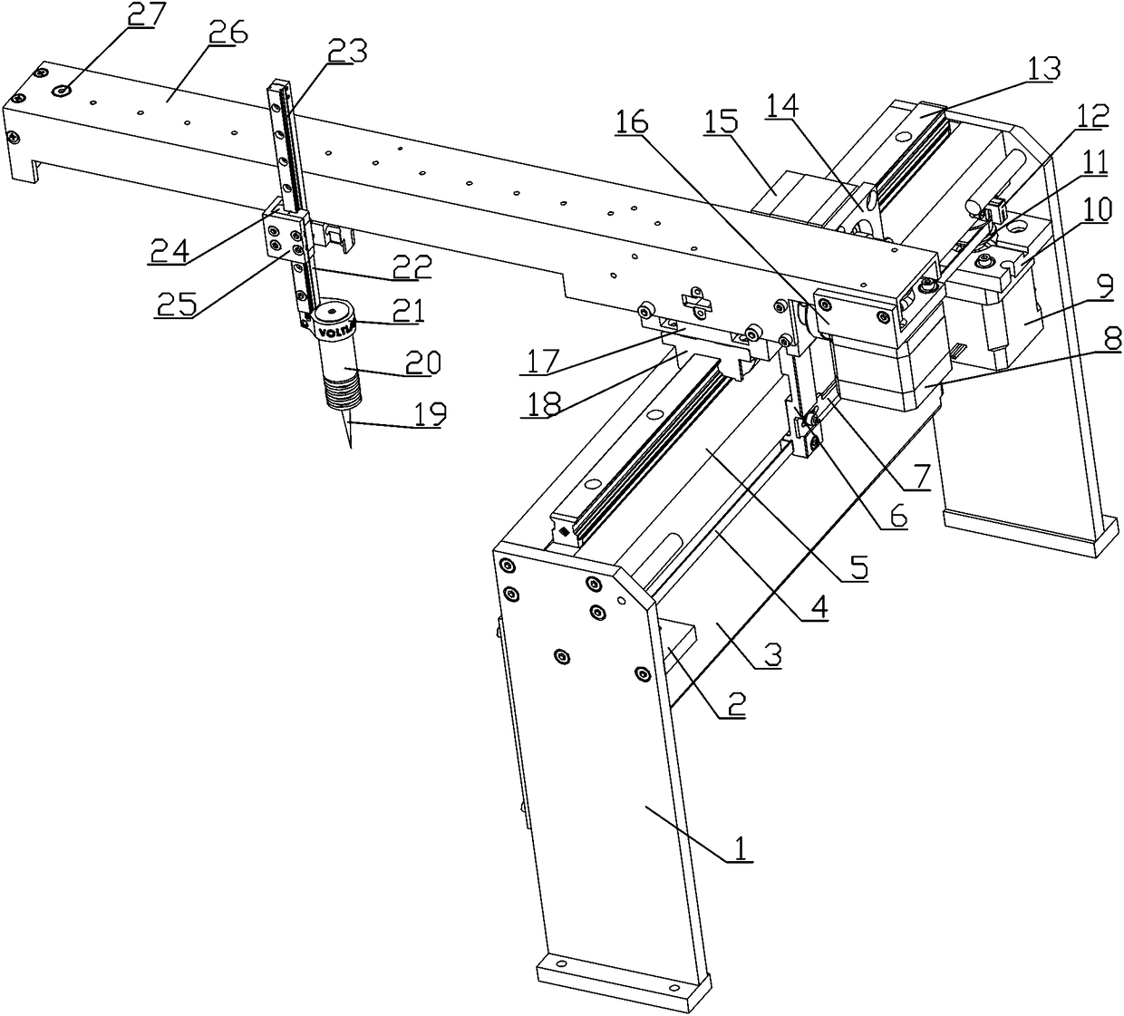
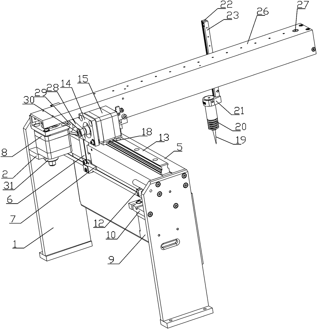
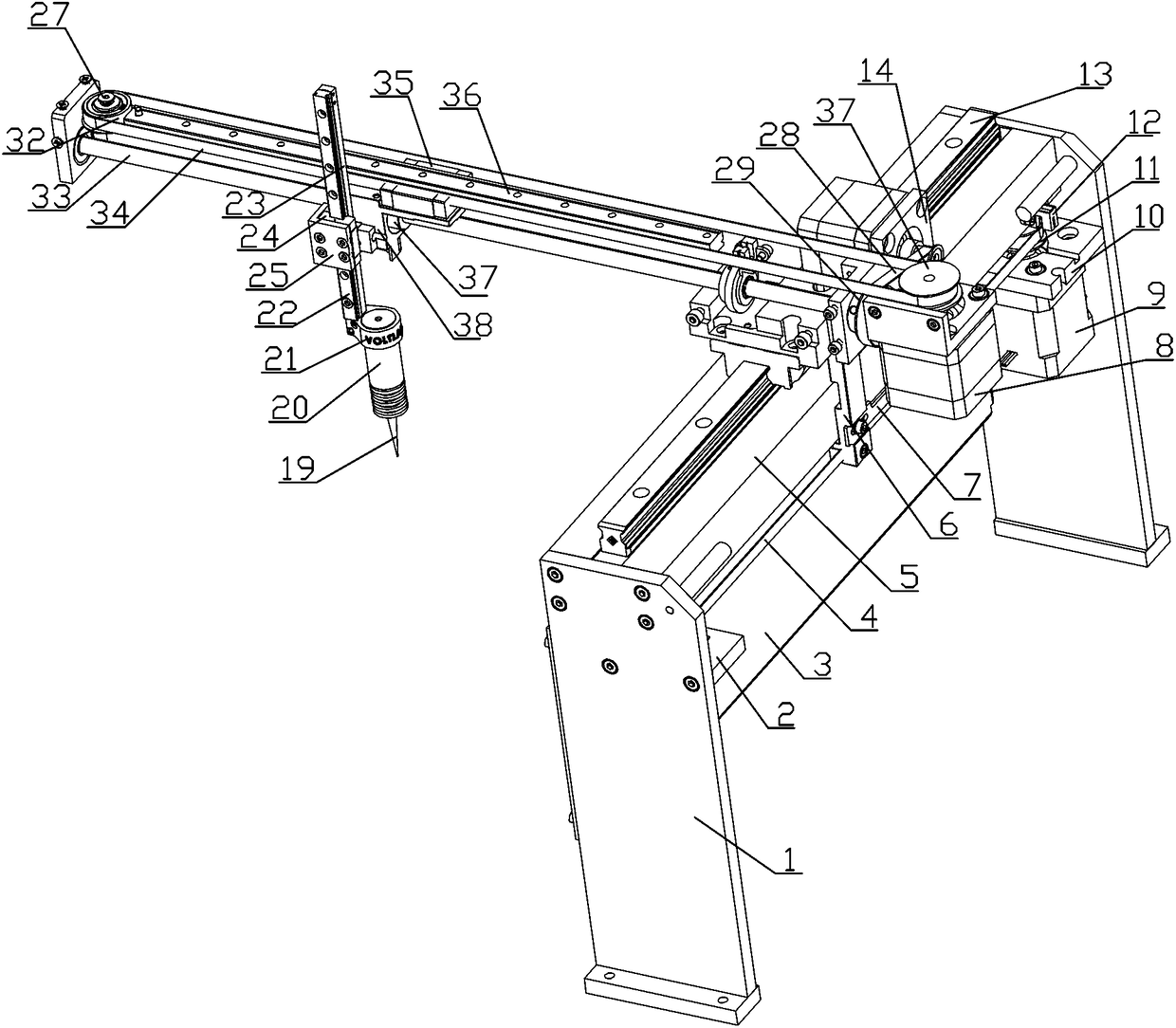
[0037] see Figure 1-5 , building formwork automation drilling machine, it comprises the frame plate 1 that symmetrical arrangement is arranged, and the top of frame plate 1 is fixed with crossbeam 5, and the top of described crossbeam 5 is equipped with transverse slide rail 13, and on described transverse slide rail 13 Sliding fit is equipped with slide block 18, and the top of described slide block 18 is fixed with transverse sliding plate 17, and vertical connecting plate 6 is installed on the side wall of described transverse sliding plate 17, and described vertical connecting plate 6 and The transverse power device used to drive the movement of the transverse sliding plate 17 is connected; the side wall of the transverse sliding plate 17 is fixed with a longitudinal motor mounting plate 16, and a horizontally arranged cantilever box is installed on the longitudinal motor mounting plate 16 26. A longitudinal sliding mechanism for providing longitudinal movement is install...

Embodiment 2

[0047] The operating method of any one of the building formwork automation drilling machines, it comprises the following steps:

[0048] Step1: Fix this automatic drilling machine on the side of the building formwork;

[0049] Step2: According to the required drilling position, the PLC controller controls the horizontal movement motor 9 and the longitudinal movement motor 8 respectively, and drives the drilling device to move within the plane range, so that it moves directly above the required drilling position;

[0050] Step3: Control the vertical lifting motor 15 through the PLC controller, drive the drilling device to move up and down through the vertical lifting motor 15, and then control the lifting of the drilling device;

[0051] Step4: Start the drilling machine 20 after the drill bit 19 is in place, and drill the template through the drilling machine 20;

[0052] Step5: After one hole is drilled, proceed to the next hole.


PUM


Abstract

The invention provides a building template automatic drilling machine and an operating method. A transverse beam is fixed to the tops of rack plates; a transverse sliding rail is installed at the topof the transverse beam; a sliding block is installed on the transverse sliding rail in a sliding fit manner; a transverse sliding plate is fixed to the top of the sliding block; a vertical connectingplate is installed on the side wall of the transverse sliding plate and is connected with a transverse power device; the transverse power device is used for driving the transverse sliding plate to move; a longitudinal motor mounting plate is fixed to the side wall of the transverse sliding plate; a cantilever box body horizontally arranged is installed on the longitudinal motor mounting plate; a longitudinal sliding mechanism used for providing longitudinal movement is installed in the cantilever box body; a vertical lifting mechanism used for providing lifting movement is installed on the longitudinal sliding mechanism; and a drilling device used for drilling is installed at the tail end of a lifting sliding rail of the vertical lifting mechanism. The automatic drilling machine can be used for automatic drilling of a building template, so that the drilling efficiency and the drilling quality are further improved effectively.

Description

technical field [0001] The invention relates to the field of building processing equipment, in particular to an automatic drilling machine for building templates and an operating method. Background technique [0002] In the process of building construction, a large number of formwork is needed. In order to meet the needs of installation and use, it is usually necessary to drill holes in the formwork. Multiple through holes need to be drilled on the same formwork, and the accuracy of the hole positions is high. Traditional Most of the drilling holes are artificial drilling, which has the following defects: [0003] (1) Due to the large number of holes, manual drilling is used, and the work efficiency is low; [0004] (2) The labor intensity of the operators is high, which is not conducive to long-term operations; [0005] (3) The drilling quality is not well guaranteed. Contents of the invention [0006] In order to solve the above technical problems, the present inventi...

Claims


Application Information

Patent Timeline
Patent Type & Authority Applications(China)
IPC IPC(8): B23B39/14B23Q5/38
CPCB23B39/14B23Q5/385
Inventor 胡勇
Owner 湖北绿筑装配科技有限公司
Why Eureka
Try Eureka