
Aluminum profile integrated device

A kind of aluminum profile, overall technology, applied in the direction of positioning device, clamping device, clamping, etc., can solve the problems of manual measurement, inaccurate cutting length, uneven cutting end surface, etc., and achieve the effect of avoiding scratches

Active Publication Date: 2018-10-16
ANHUI AOYU CNC TECH
View PDF6 Cites 4 Cited by
  • Summary
  • Abstract
  • Description
  • Claims
  • Application Information

AI Technical Summary

Problems solved by technology

[0002] Aluminum profiles are aluminum materials with different cross-sectional shapes obtained by hot melting and extrusion of aluminum rods. They have the characteristics of corrosion resistance, excellent electrical conductivity, high thermal conductivity, and non-ferromagnetic properties. Aluminum profiles are extruded from extrusion machines The extrusion is uninterrupted, and the length is generally relatively long. It needs to be cut into different lengths according to the needs. The current aluminum profiles need to be measured manually, and then cut with an ordinary cutting machine. However, this method is easy to cause inaccurate cutting lengths. , uneven cutting end surface and other problems, for this reason we propose an aluminum profile overall device to solve the above problems

Method used


Image

  • Aluminum profile integrated device
  • Aluminum profile integrated device
  • Aluminum profile integrated device

Examples


Embodiment Construction

[0018] The following will clearly and completely describe the technical solutions in the embodiments of the present invention with reference to the accompanying drawings in the embodiments of the present invention. Obviously, the described embodiments are only some, not all, embodiments of the present invention. Based on the embodiments of the present invention, all other embodiments obtained by persons of ordinary skill in the art without making creative efforts belong to the protection scope of the present invention.

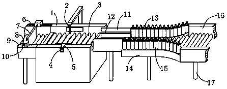
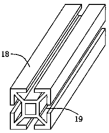
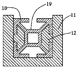
[0019] see Figure 1-4 , the present invention provides a technical solution: an integral device for aluminum profiles, including a water tank 1, a water cutting head 2 and an aluminum profile 18, T-shaped grooves 19 are opened on the sides of the aluminum profile 18, and the water cutting head 2 is installed on the outer wall of the water tank 1 On, the drive roller 3 is installed on the side plate of the inner cavity of the water tank 1, and the cylinder 4 i...


PUM


Abstract

The invention discloses an aluminum profile integrated device. The device comprises a water tank, a water cutting head and aluminum profiles; T-shaped grooves are formed in surrounding surfaces of thealuminum profiles; the water cutting head is mounted on the outer wall of the water tank; a side plate of the water tank is connected with a clamping plate; a second transmission plate is arranged atone end of the water tank; sliding chutes are formed in the second transmission plate; sliding blocks are clamped in the sliding chutes; motors are arranged outside the sliding blocks; the motors areconnected with baffles; the water tank is connected with positioning plates; positioning blocks are mounted in the positioning plates; the positioning plates are connected with guiding plates; the tops of the guiding plates are connected with guiding rolls; and one ends of the guiding plates are connected with first transmission plates. Through sliding the sliding blocks, the distance between thebaffle and the water cutting head is equal to a cutting length of the aluminum profiles, the aluminum profiles are transmitted to the guiding plates from the first transmission plates; the guiding rolls on the guiding plates rotate to adjust the aluminum profiles to a vertical state so that the aluminum profiles properly enter into the positioning plates, the positioning blocks on the positioningplates are glidingly clamped into the T-shaped grooves on the aluminum profiles, the clamping plates clamp the aluminum profiles, the water cutting head cuts the aluminum profiles, and after the cutting is finished, the aluminum profiles are transmitted away from the second transmission plates.

Description

technical field [0001] The invention relates to the technical field of cutting equipment, in particular to an integral device for aluminum profiles. Background technique [0002] Aluminum profiles are aluminum materials with different cross-sectional shapes obtained by hot melting and extrusion of aluminum rods. They have the characteristics of corrosion resistance, excellent electrical conductivity, high thermal conductivity, and non-ferromagnetic properties. Aluminum profiles are extruded from extrusion machines The extrusion is uninterrupted, and the length is generally relatively long. It needs to be cut into different lengths according to the needs. The current aluminum profiles need to be measured manually, and then cut with an ordinary cutting machine. However, this method is easy to cause inaccurate cutting lengths. , Uneven cutting end surface and other problems, for this reason we propose an aluminum profile overall device to solve the above problems. Contents of...

Claims


Application Information

Patent Timeline
IPC IPC(8): B23D79/00B23Q7/00B23Q3/08B23Q17/22
CPCB23D79/00B23Q3/08B23Q7/00B23Q17/2233B23Q2703/04
Inventor 徐昆
Owner ANHUI AOYU CNC TECH
Learn More