An anchor chain rail welding system

A welding system and anchor chain technology, applied in welding equipment, auxiliary welding equipment, welding/cutting auxiliary equipment, etc., can solve the problems that the welding quality cannot be guaranteed, automation cannot be completed, and the installation space requirements are high, and the design is simple and reliable. , Compact structure, high turnover efficiency

Active Publication Date: 2020-11-13
JIANGSU SHUOSHI WELDING SCI & TECH +1
View PDF2 Cites 0 Cited by
  • Summary
  • Abstract
  • Description
  • Claims
  • Application Information

AI Technical Summary

Problems solved by technology

[0003] Chinese patent application No. 201110136523.5 discloses an automatic welding device for anchor chain crosspieces. Although the device discloses automatic welding for anchor chain crosspieces, the device still needs to be manually turned over during the welding process, which cannot be automated, and Can not guarantee the quality of welding
[0004] Chinese patent application No. 201010170387.7 discloses an automatic welding device and automatic welding method for anchor chains and mooring chain crosspieces. Although the device utilizes the transverse chain plate of the right-angled conveying chain plate and the linear conveying chain, the plates are parallel and located on the straight line. Right below the conveyor chain plate, it can be flipped to a certain extent, but the device has high space requirements and the welding angle is fixed, which does not meet the actual needs

Method used


Image

  • An anchor chain rail welding system

Examples


Embodiment 1

[0027] The technical solution of the present invention will be described in further detail below in conjunction with the accompanying drawings.

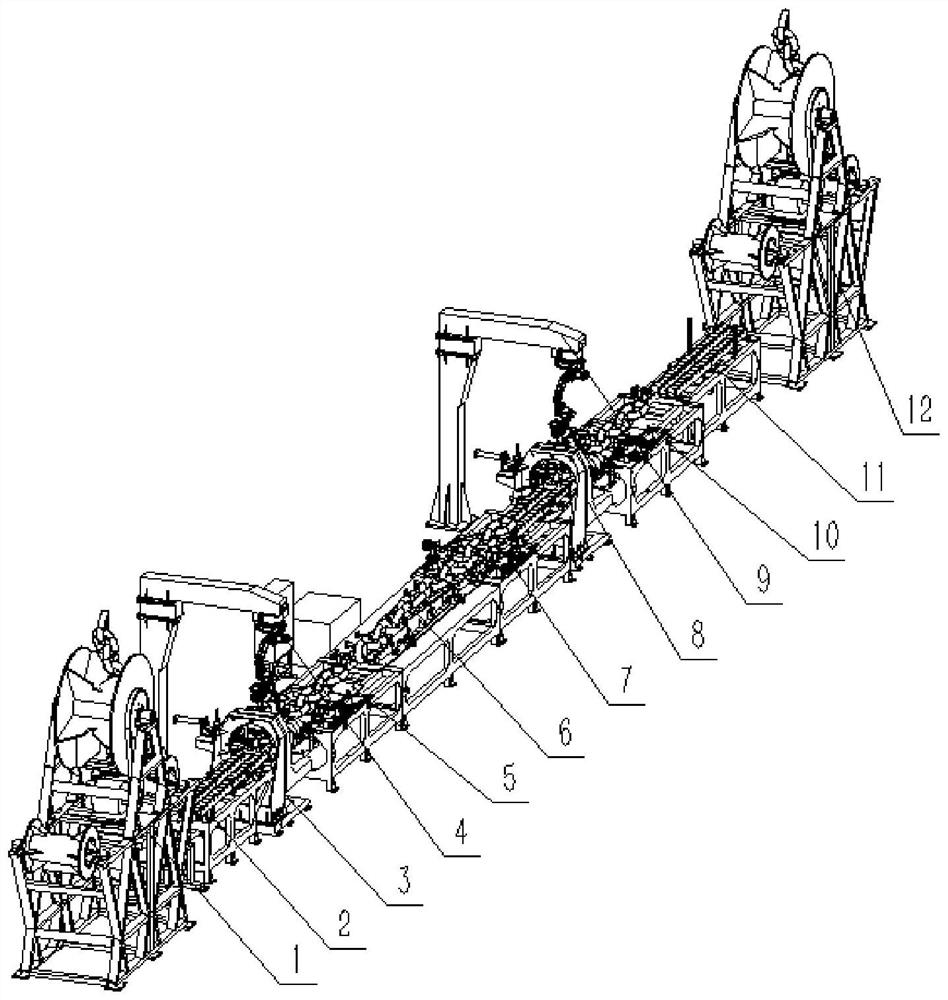
[0028] Such as figure 1 , an anchor chain crosspiece welding system, comprising:

[0029] A feeding mechanism 1, a correspondingly arranged discharging mechanism 12;

[0030] Also includes: conveyor system, welding robot system;

[0031] Wherein, the feeding mechanism 1, the conveying system and the discharging mechanism 12 are located at both ends of the welding system, and the conveying system includes a first auxiliary mechanism 2 connected with the feeding mechanism 1, and a second auxiliary mechanism 11 connected with the discharging mechanism 12. And multiple thrust mechanisms located at the end of the above-mentioned anchor chain conveying output mechanism and the welding processing end in the middle;

[0032] The above-mentioned transmission line at the middle welding processing end is a mechanism that passes through the f...


PUM


Abstract

The invention discloses an anchor chain crosspiece welding system. The anchor chain crosspiece welding system comprises a feeding mechanism and a discharging mechanism, wherein the discharging mechanism is arranged corresponding to the feeding mechanism; the device further comprises a conveying system and a welding robot system, wherein the feeding mechanism, the conveying system and the discharging mechanism are located at the two ends of the welding system, the conveying system comprises a first auxiliary mechanism connected with the feeding mechanism, a second auxiliary mechanism connectedwith the discharging mechanism, and a plurality of thrust mechanisms which are correspondingly located at the conveying mechanism end, the output mechanism end and the middle welding machining end ofan anchor chain; a transmission line of the middle welding machining end is a mechanism which is arranged in a mode of penetrating through a first position changing device and a second position changing device; workpiece turnover mechanisms are arranged between the position changing device and the second position changing device; and a first robot welding system and a second robot welding system are arranged at the rear ends of the position changing device and the second position changing device respectively. The automatic anchor chain crosspiece welding system has the advantages of being highin production efficiency, good in equipment reliability, stable in welding quality, simple to operate, convenient to maintain and the like.

Description

technical field [0001] The invention relates to an automatic welding production line, in particular to an automatic welding system applied to anchor chain crosspieces. Background technique [0002] The anchor chain is the chain connecting the anchor and the hull, which is used to transmit and buffer the external force on the ship. The anchor chain is made up of many chain links, and the size is expressed in chain diameter (mm). According to whether there is a brace in the middle of the chain link, it is divided into a chain anchor chain and a chain anchor chain without a chain link. The crosspiece of the chain anchor chain needs to be welded together with the chain link, the welding is firm and reliable, and the weld seam looks beautiful. At present, manual welding is used in the industry. After one side is welded, it needs to be manually flipped and then welded on the other side. The labor intensity is very high, the risk is high, the working environment is harsh, and th...

Claims


Application Information

Patent Timeline
Patent Type & Authority Patents(China)
IPC IPC(8): B23K37/00B23K37/04B23K37/047
CPCB23K37/00B23K37/04B23K37/047
Inventor 王波周琦唐郭
Owner JIANGSU SHUOSHI WELDING SCI & TECH
Why Eureka
Try Eureka