
Pneumatic launching system for vehicle-mounted loitering unit

A launching system and patrolling vehicle technology, which is applied in the field of vehicle-mounted weapon launch, can solve the problems of bulky gas source occupying space, spark or hot gas spraying into the vehicle interior, and poor safety, so as to ensure the stability and safety of work and enhance safety Sexuality and work reliability, the effect of high work efficiency

Pending Publication Date: 2018-10-16
北京中资燕京汽车有限公司
View PDF0 Cites 5 Cited by
  • Summary
  • Abstract
  • Description
  • Claims
  • Application Information

AI Technical Summary

Problems solved by technology

[0002] At present, weapon launching devices such as cruisers loaded on armored vehicles and other military vehicles usually use thermal power generated by ignition to launch weapons. This launching method is only suitable for loading on the roof or elevating launching devices. , the ignition type launch is easy to spray sparks or hot gas into the vehicle interior, damaging the vehicle, and at the same time, the temperature of the launch device itself is high, which affects the life of the device; there is also a plan to use pneumatic launch, but this method generally uses the gas source provided by an external gas tank, etc. , this kind of gas source is generally bulky, takes up a lot of space, has limited capacity, is easy to interrupt the gas supply, and has poor safety

Method used


Image

  • Pneumatic launching system for vehicle-mounted loitering unit
  • Pneumatic launching system for vehicle-mounted loitering unit
  • Pneumatic launching system for vehicle-mounted loitering unit

Examples


Embodiment Construction

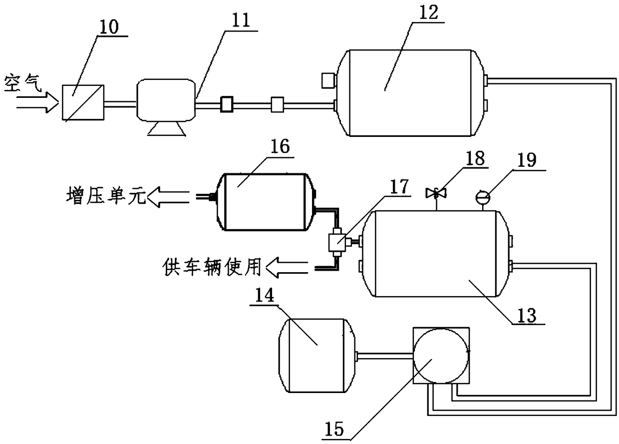
[0032] Aiming at the disadvantages of poor safety performance and narrow scope of application of the thermodynamic launch method adopted by the existing military vehicle cruiser and other weapon launchers, and the existing pneumatic launch method has defects such as easy interruption of external air source supply and large space occupation, the present invention A vehicle-mounted cruiser pneumatic launch system is provided. The system uses the vehicle-mounted air source device of the military vehicle to purify, compress, and dry the air, then stores the gas in a dry gas storage tank, and stores the dry gas The excess low-pressure gas in the tank is taken out, pressurized and distributed, and enters the cruiser launching tube, and the impact force of the high-pressure gas is used to launch the cruiser, and the vehicle's own gas source is used as the power of the vehicle-mounted cruiser launch system of the present invention. source, low cost, continuous gas supply, safe and reli...


PUM


Abstract

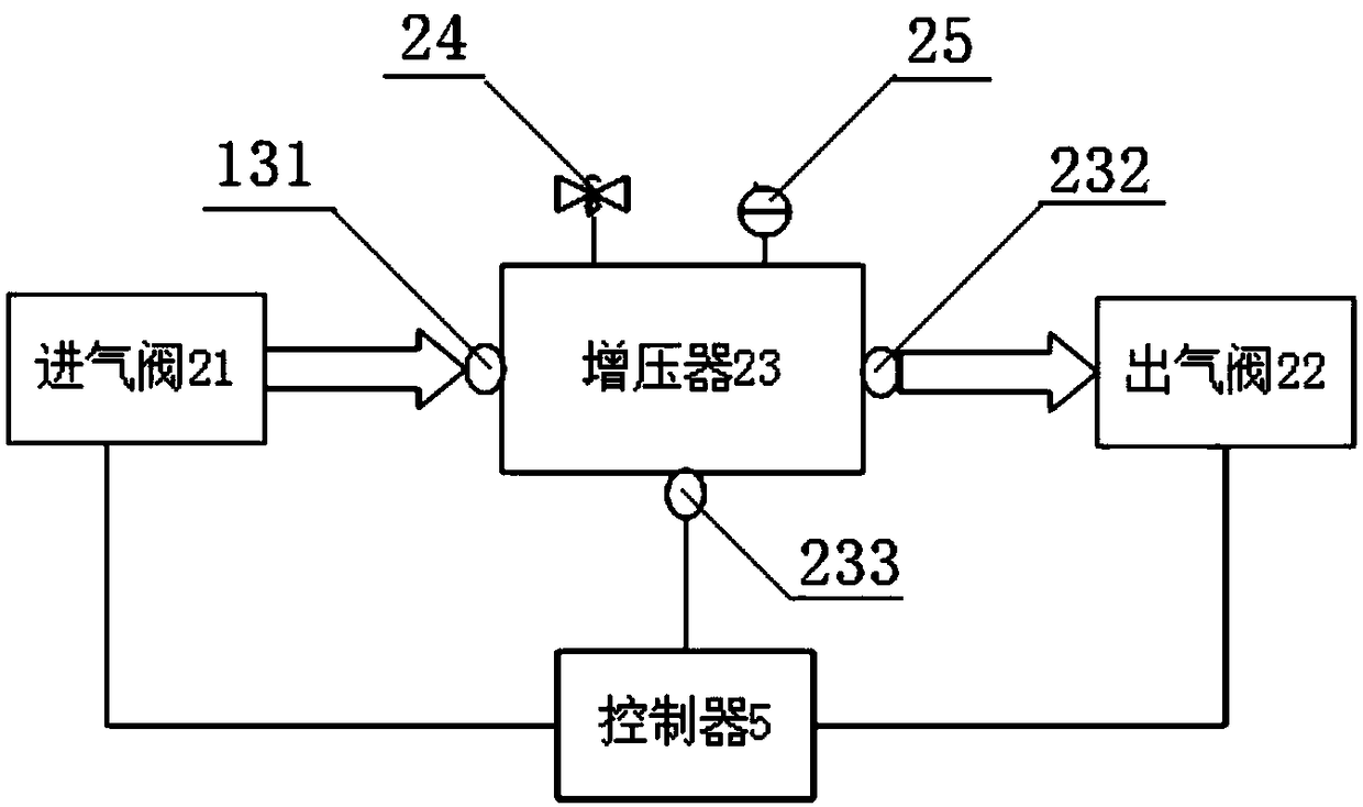
The invention provides a pneumatic launching system for a vehicle-mounted loitering unit, and belongs to the technical field of vehicle-mounted weapon launching. The pneumatic launching system comprises a vehicle-mounted air source device, a pressurization unit, a high-pressure air distribution unit and a launching unit which communicate with each other in sequence through air flues. The launchingunit is provided with a launching tube, the launching tube is internally provided with a piston, the periphery of the piston is in contact with the inner wall of the launching tube and can slide along the inner wall of the launching tube, and the piston and the bottom of the launching tube form a sealing cavity. A launching cover is arranged at an outlet of the launching tube, and the loitering unit is located between the piston and the launching cover. According to the pneumatic launching system for the vehicle-mounted loitering unit, an own vehicle-mounted air source device of a vehicle isused, air is used as the raw material to realize continuous air supply to overcome the defect that air supply by an external air tank mode is prone to being interrupted, the cost is saved, and the working efficiency is high; a safety valve and a pressure gauge are arranged additionally to prevent excessive gas pressure during the working process, and the safety and working reliability of gas compression are enhanced; and by arranging buffer mechanisms such as a buffer tank, the work stability and security are guaranteed.

Description

technical field [0001] The invention belongs to the technical field of vehicle-mounted weapon launch, relates to a pneumatic launch technology, and in particular to a pneumatic launch system for a vehicle-mounted cruiser with simple structure, convenient use, safety and reliability. Background technique [0002] At present, weapon launching devices such as cruisers loaded on armored vehicles and other military vehicles usually use thermal power generated by ignition to launch weapons. This launching method is only suitable for loading on the roof or elevating launching devices. , the ignition type launch is easy to spray sparks or hot gas into the vehicle interior, damaging the vehicle, and at the same time, the temperature of the launch device itself is high, which affects the life of the device; there is also a plan to use pneumatic launch, but this method generally uses the gas source provided by an external gas tank, etc. , This type of gas source is generally bulky, tak...

Claims


Application Information

Patent Timeline
IPC IPC(8): B64F1/06
CPCB64F1/06B64U70/70B64U80/86
Inventor 杨森
Owner 北京中资燕京汽车有限公司
Learn More