Method for generating circularly polarized vortex electromagnetic waves

A vortex electromagnetic wave and generation method technology, which is applied to electrical components, electrical digital data processing, radio transmission systems, etc., can solve the problems of low conversion efficiency, difficult processing, complex structure, etc., and achieve low cost, convenient application, and control high precision effect

Active Publication Date: 2018-10-16
XIAN INSTITUE OF SPACE RADIO TECH
View PDF7 Cites 7 Cited by
  • Summary
  • Abstract
  • Description
  • Claims
  • Application Information

AI Technical Summary

Problems solved by technology

[0004] The technical problem solved by the present invention is: to overcome the problems of complex structure, difficult processing and low conversion efficiency of the current circularly polarized vortex electromagnetic wave generating device based on the phased array system and reflector antenna, the present invention provides a circula

Method used


Image

  • Method for generating circularly polarized vortex electromagnetic waves
  • Method for generating circularly polarized vortex electromagnetic waves
  • Method for generating circularly polarized vortex electromagnetic waves

Examples


Embodiment 1

[0085] Embodiment 1: Feed forward feed, it is expected to generate a vortex beam with modal number L=-2 along the normal direction

[0086] Step 1: Set input conditions

[0087] (1) Frequency f=9GHz;

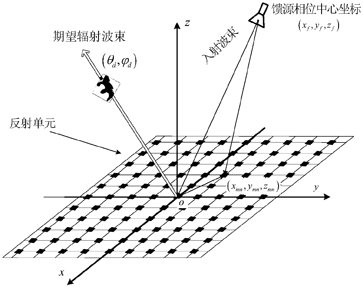
[0088] (2) Feed location (x f ,y f ,z f )=(0,0,233mm);

[0089] (3) Array parameter M=N=25, d x = d y = 10mm;

[0090] (4) Orbital angular momentum mode L=-2;

[0091] (5) Main radiation direction

[0092] Step 2: Calculate the spatial phase delay distribution from the feed to the surface of the reflectarray, such as Figure 6 shown.

[0093] Step 3: Calculate the expected phase distribution on the surface of the reflectarray, such as Figure 7 shown. Since the expected mode number L=-2, the phase along the azimuth direction exhibits two periods of variation, which is the same as expected.

[0094] Step 4: Calculate the rotation angle distribution of the reflectarray unit, such as Figure 8 shown. The expected beam is along the normal direction, and the expected...

Embodiment 2

[0097] Embodiment 2: Feed bias feed, expected to produce edge Vortex beam with directional mode number L=1

[0098] Step 1: Set input conditions

[0099] (1) Frequency f=9GHz;

[0100] (2) Feed location (x f ,y f ,z f )=(0,0,233mm);

[0101] (3) Array parameter M=N=25, d x = d y = 10mm;

[0102] (4) Orbital angular momentum mode L=1;

[0103] (5) Main radiation direction

[0104] Step 2: Calculate the spatial phase delay distribution from the feed to the surface of the reflectarray, such as Figure 12 shown.

[0105] Step 3: Calculate the expected phase distribution on the surface of the reflectarray, such as Figure 13 shown. Since the expected mode number L=1, the phase along the azimuth direction exhibits two periods of variation, which is the same as expected.

[0106] Step 4: Calculate the rotation angle distribution of the reflectarray unit, such as Figure 14 shown. The expected beam is along the normal direction, and the expected phase of the reflect...


PUM


Abstract

A method for generating circularly polarized vortex electromagnetic waves comprises the following steps: (1) setting parameters; (2) calculating the spatial phase delay distribution from a feed sourceto the surface of a reflective array; (3) calculating the desired phase distribution of the surface of the reflective array so that an antenna can radiate vortex electromagnetic waves along the direction as defined in the description; (4) calculating the rotation angle distribution of a reflective array element; (5) according to the rotation angle of the reflective array element, establishing a full-wave simulation model of the surface of the reflective array; and (6) performing numerical value calculation on the full-wave simulation model of the reflective array and calculating to obtain full-wave simulation results of an amplitude pattern and a phase pattern of the reflective array. The invention effectively solves the problems of complex structure, large processing difficulty and lowconversion efficiency of the existing circularly polarized vortex electromagnetic wave generating device, can be used as a transmitting antenna or a receiving antenna of a circularly polarized OAM communication system, and can improve communication capacity.

Description

technical field [0001] The invention belongs to the technical field of antennas and relates to a method for generating circularly polarized vortex electromagnetic waves. Background technique [0002] With the maturity of various multiplexing technologies such as polarization multiplexing, orthogonal frequency division multiplexing, code division multiple access and co-frequency duplexing, how to further improve spectrum utilization and coding efficiency has become a research hotspot in the field of wireless communication today. . Orbital angular momentum can provide a new multiplexing dimension for radio multiplexing technology. Theoretically, an electromagnetic wave of a single frequency has infinitely many OAM modes, and each mode can transmit information independently, realizing the so-called "state division multiplexing". The channel of the OAM communication system has infinitely many dimensions, so the channel capacity of radio communication, optical communication and...

Claims


Application Information

Patent Timeline
IPC IPC(8): G06F17/50H04B7/00
CPCH04B7/00G06F30/20
Inventor 王建晓尚社宋大伟孙文锋李栋罗熹温媛媛范晓彦
Owner XIAN INSTITUE OF SPACE RADIO TECH
Why Eureka
Try Eureka