Moving image defogging method for capsule floor heating system

A technology of moving images and capsules, applied in the field of floor heating, can solve the problems of inability to achieve clear monitoring, easy to shoot foggy images, and unsatisfactory monitoring effects.

Inactive Publication Date: 2018-10-16
毛述春
View PDF0 Cites 0 Cited by
  • Summary
  • Abstract
  • Description
  • Claims
  • Application Information

AI Technical Summary

Problems solved by technology

In addition, when the image moves under the ground, due to the temperature difference between the inside and outside, the temperature of the capsule and the temperature difference in the space inside the track, the lens ca

Method used


Image

  • Moving image defogging method for capsule floor heating system
  • Moving image defogging method for capsule floor heating system
  • Moving image defogging method for capsule floor heating system

Examples


Embodiment Construction

[0060]The technical solutions in the embodiments of the present invention will be described clearly and in detail below with reference to the drawings in the embodiments of the present invention. The described embodiments are only some of the embodiments of the invention.

[0061] The technical scheme that the present invention solves the problems of the technologies described above is:

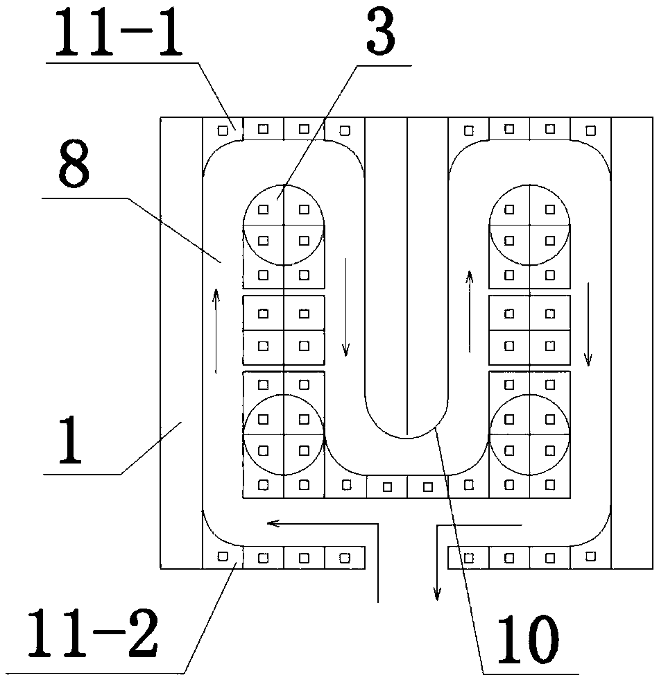
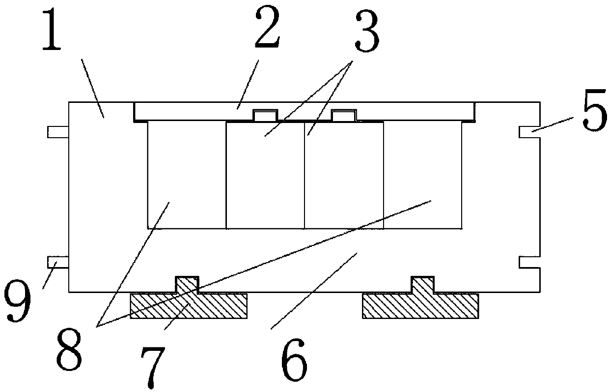
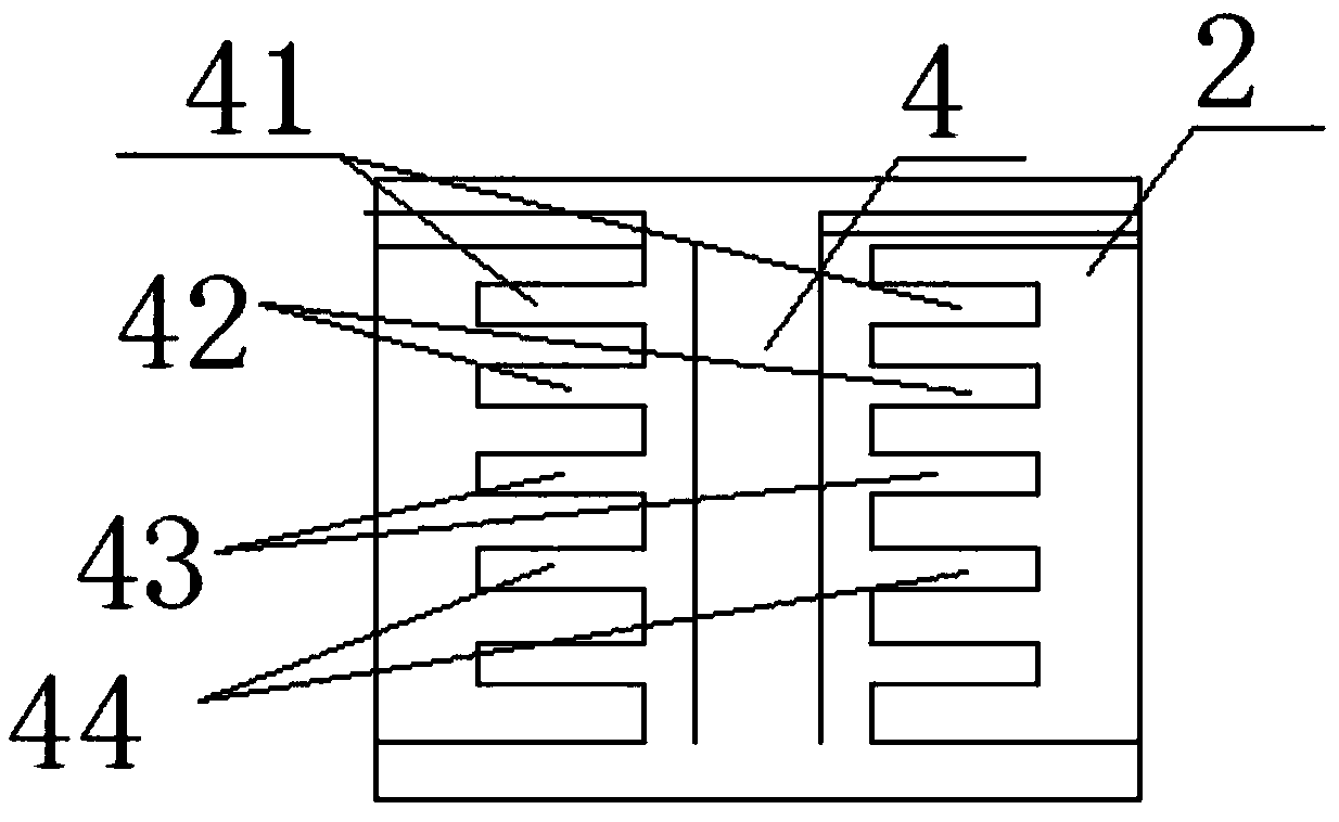
[0062] Such as Figure 9 Shown is a capsule floor heating system, which includes a combined floor heating track, a capsule floor heating heating device, a ground control and command device, and a ground heating pile. The combined floor heating track is assembled and installed by several track modules to form a floor heating track. The movement of the capsule floor heating device heats the indoor space, and the ground control and command device realizes the advancement and movement of the capsule floor heating device, and the heating unit is heated through the ground heating pile.

[0063] S...


PUM


Abstract

The present invention claims a moving image defogging method for a capsule floor heating system. The method comprises the steps of: acquiring a moving image of a floor heating capsule system, enhancing an original fog image by using sub-block partially overlapped local histogram equalization, and obtaining the optimized transmittance through a DCP algorithm; using constraint characteristics of anMRF model to the image structure details to perform modeling on the transmittance so as to further refine the transmittance; and through the salient features of the sky domain, obtaining the atmospheric light value by using the sub-block search method. According to the method provided by the present invention, a more accurate transmittance image can be obtained, image structure information can beeffectively maintained, and the defogged image presents rich details and a more realistic color visual effect; and the capsule floor heating system is easy and convenient to install, and an intuitiveand vivid visualized modular floor heating track is innovatively invented.

Description

technical field [0001] The invention belongs to the technical field of floor heating, and in particular relates to a moving image defogging method of a capsule floor heating system. Background technique [0002] Among the existing floor heating equipment, hydroelectric floor heating, the medium is water and electricity, heated by water and electricity, and then passed through the pipeline and the insulation layer without moving, directly buried and backfilled for secondary heat dissipation, consumes a lot of heat resources, and the initial temperature is slow , the operating cost is high, and the unsafe problem of water leakage and electricity leakage in concealed projects cannot be avoided, and the worry about the future is that it cannot be repaired. Existing floor heating uses water or electricity to flow in the pipeline, and the heat transfer is realized through the flow of water, and the heat storage time is longer. The traditional concept is that water or electricity m...

Claims


Application Information

Patent Timeline
IPC IPC(8): G06T5/00G06T7/90F24D13/02
CPCG06T5/003F24D13/024G06T7/90
Inventor 毛述春
Owner 毛述春
Why Eureka
Try Eureka