A non-contact low passive intermodulation waveguide connection structure and design method

A non-contact, passive intermodulation technology, applied in the microwave field, can solve problems such as the inability to fundamentally eliminate contact nonlinearity, unusable products for reliability, and inability to achieve broadband performance, so as to suppress passive intermodulation effects, The effect of compact structure and good tolerance

Active Publication Date: 2022-03-04
XIAN INSTITUE OF SPACE RADIO TECH
View PDF3 Cites 0 Cited by
  • Summary
  • Abstract
  • Description
  • Claims
  • Application Information

AI Technical Summary

Problems solved by technology

In addition to the structure of the pressurized table, the high-pressure flange also needs to ensure a high enough smoothness of the contact surface and precise torque tightening, which has high requirements for processing and assembly technology, and due to the existence of contact, it is impossible to fundamentally eliminate contact nonlinearity , there is a long-term reliability problem
The dielectric film isolation method cannot be used in actual products due to reliability issues
Although the choke (choke) flange avoids part of the electrical contact, but because its main structure is a quarter-wavelength choke slot, it cannot achieve broadband performance, and the working bandwidth is narrow, which is also limited in practical applications.

Method used


Image

  • A non-contact low passive intermodulation waveguide connection structure and design method
  • A non-contact low passive intermodulation waveguide connection structure and design method
  • A non-contact low passive intermodulation waveguide connection structure and design method

Examples


Embodiment Construction

[0028] Exemplary embodiments of the present disclosure will be described in more detail below with reference to the accompanying drawings. Although exemplary embodiments of the present disclosure are shown in the drawings, it should be understood that the present disclosure may be embodied in various forms and should not be limited by the embodiments set forth herein. Rather, these embodiments are provided for more thorough understanding of the present disclosure and to fully convey the scope of the present disclosure to those skilled in the art. It should be noted that, in the case of no conflict, the embodiments of the present invention and the features in the embodiments can be combined with each other. The present invention will be described in detail below with reference to the accompanying drawings and examples.

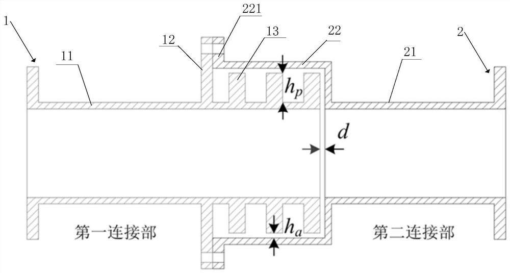
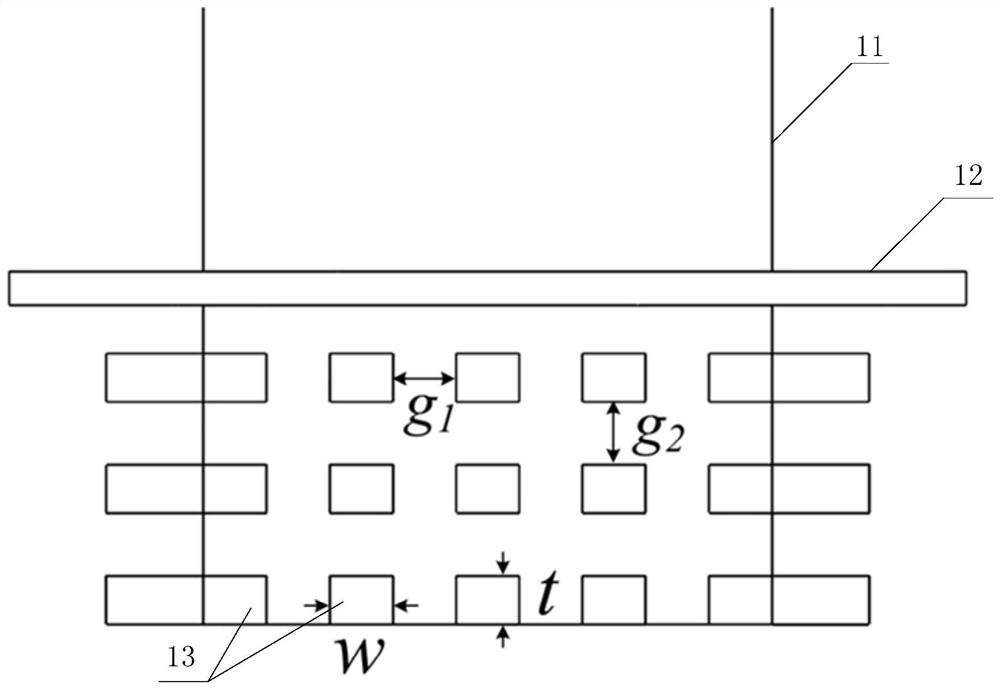
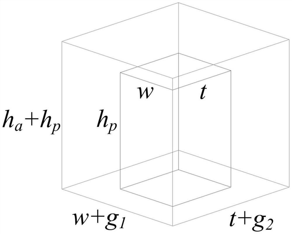
[0029]This embodiment proposes a non-contact low passive intermodulation waveguide connection structure, by designing a periodic metal convex structure around...


PUM


Abstract

The invention discloses a non-contact low passive intermodulation waveguide connection structure and a design method. Periodic metal protrusions are designed on the outer wall of the waveguide as a first connection part. A stepped waveguide with matching dimensions is designed at the end of the other waveguide as the second connection part. The first connection part is embedded in the second connection part, and an internal non-contact waveguide connection structure is formed through mechanical connection. Calculate the parameters such as the size of the convex body and the internal spacing of the connecting structure to obtain the appropriate electromagnetic band gap characteristics and realize the suppression of electromagnetic leakage in the structural gap. The non-contact low passive intermodulation waveguide connection structure proposed in the present invention realizes the internal non-contact of the waveguide connection without affecting the electromagnetic transmission, eliminates the contact nonlinearity of the traditional connection, and effectively suppresses the passive intermodulation effect. And reduce the requirements on materials, processing and assembly technology. At the same time, it has the advantages of broadband, compact structure, strong tolerance, etc., and can be applied to various high-power and low passive intermodulation microwave components and test systems.

Description

technical field [0001] The invention relates to a non-contact low passive intermodulation waveguide connection structure and design method, which can be used in various high-power low passive intermodulation microwave components and test systems, and belongs to the field of microwave technology. Background technique [0002] Passive Intermodulation (PIM) effect is an important interference phenomenon in communication systems, which widely exists in various high-power microwave passive components and connection structures. The main mechanism of passive intermodulation is contact nonlinearity and material nonlinearity. Material nonlinearity can be avoided by choosing appropriate materials, while contact nonlinearity generally exists in various microwave passive structures. The waveguide structure is one of the most widely used structural forms in various high-power microwave systems, and the waveguide flange connection is the primary factor for passive intermodulation in the w...

Claims


Application Information

Patent Timeline
Patent Type & Authority Patents(China)
IPC IPC(8): H01P1/04H01P11/00
CPCH01P1/042H01P11/00
Inventor 陈翔孙冬全崔万照
Owner XIAN INSTITUE OF SPACE RADIO TECH
Why Eureka
Try Eureka